 +86-13867573512
 [email protected]
Bearing Types, Selection, Lubrication & Failure Prevention Guide
Author: Heyang Date: Apr 27, 2026
Content
- 1 What Is a Bearing and Why Does It Matter in Every Machine
- 2 The Main Types of Bearings and What Each One Is Built For
- 3 How to Select the Right Bearing for Any Application
- 4 Bearing Lubrication: The Factor That Controls 80% of Service Life
- 5 Bearing Failure: The Four Stages and What Causes Them
- 6 Bearing Installation: Where Most Preventable Failures Begin
- 7 Bearing Materials and Coatings: Matching Construction to Conditions
- 8 Bearing Condition Monitoring: Moving from Reactive to Predictive Maintenance
- 9 Bearing Applications Across Industries: From Automotive to Aerospace
- 10 Practical Bearing Maintenance Checklist for Industrial Equipment
What Is a Bearing and Why Does It Matter in Every Machine
A bearing is a mechanical component designed to constrain relative motion between parts and reduce friction between moving surfaces. In plain terms, it allows one part to rotate or slide smoothly against another without direct metal-to-metal contact — and that single function keeps nearly every piece of machinery on the planet running. Without bearings, modern industry would not exist. Electric motors, automotive drivetrains, wind turbines, conveyor systems, aerospace equipment, household appliances — all depend on bearings to transfer loads and permit precise motion.
The core job of any bearing is straightforward: support a load while allowing movement. But the engineering details behind how different bearing types accomplish that task vary widely. The choice between a ball bearing, roller bearing, plain bearing, or fluid bearing changes everything about performance, lifespan, noise level, and maintenance cost. Understanding those differences is not academic — it directly affects machine reliability and operating efficiency.
This article covers the main bearing types, how to select the right one, what causes them to fail, and how to extend service life through proper lubrication and maintenance. Whether you are an engineer specifying components or a technician troubleshooting a machine, the practical details here apply directly to your work.
The Main Types of Bearings and What Each One Is Built For
Bearings divide broadly into rolling-element bearings and plain (sliding) bearings, with fluid bearings and magnetic bearings representing specialized categories. Within rolling-element designs, the geometry of the rolling element — ball, cylinder, cone, needle — determines load capacity, speed capability, and the direction of loads the bearing can handle.
Deep Groove Ball Bearings
Deep groove ball bearings are the most widely used bearing type in the world. Their deep raceway grooves allow them to handle both radial loads (perpendicular to the shaft) and axial loads (along the shaft axis) simultaneously. They run with low friction even at high rotational speeds, generate minimal noise and vibration, and require very little maintenance. Single-row configurations are standard in electric motors, gearboxes, pumps, and household appliances. Double-row variants carry heavier combined loads in compact housings. Their versatility, availability in countless standard sizes, and low cost make deep groove ball bearings the default choice when no specific load condition rules them out.
Tapered Roller Bearings
Tapered roller bearings feature conical rolling elements and raceways arranged so that lines drawn through the roller and raceway contact surfaces converge at a single point on the bearing axis. This geometry allows them to carry heavy radial loads and heavy axial loads at the same time. They are the standard choice for automotive wheel hubs, differential gears, and heavy-duty gearboxes. One important characteristic: tapered roller bearings must be mounted in matched pairs, opposing each other, since a single row can only handle axial load in one direction. Preload must be carefully controlled during installation to avoid premature wear or overheating.
Angular Contact Ball Bearings
Angular contact ball bearings have raceways offset from each other at a defined contact angle, typically 15°, 25°, or 40°. Higher contact angles mean greater axial load capacity but reduced radial capacity. They are engineered for high-precision, high-speed applications where combined radial and axial loads exist simultaneously. Machine tool spindles, turbochargers, and precision pumps commonly use angular contact ball bearings. Like tapered roller bearings, they are often mounted in pairs or sets to handle bidirectional axial loads.
Cylindrical Roller Bearings
Cylindrical rollers provide a line contact with the raceway rather than a point contact, distributing load over a larger area. This gives cylindrical roller bearings significantly higher radial load capacity compared to ball bearings of the same physical size. They also resist shock loading and handle small amounts of misalignment better than most ball bearing designs. Applications include heavy industrial machinery, large electric motors, rolling mills, and railway axle boxes. Their moderate axial load capacity limits their use in applications with heavy thrust loads.
Spherical Roller Bearings
Spherical roller bearings have two rows of barrel-shaped rollers running in a common spherical outer raceway. This design gives them the ability to accommodate angular misalignment between the shaft and housing — typically up to 1° to 2.5° depending on the series — without causing additional stress on the bearing. This self-aligning capability makes them the bearing of choice for large industrial machinery, mining equipment, paper mills, and crushing applications where shaft deflection or housing misalignment is unavoidable. They carry very high radial loads and substantial axial loads in both directions.
Needle Roller Bearings
Needle roller bearings use cylindrical rollers with a high length-to-diameter ratio — typically at least 4:1. This gives them exceptional radial load capacity relative to their cross-sectional size. In applications where space is limited but loads are significant, needle roller bearings are often the only practical solution. Automotive drivetrains use them extensively in gearboxes, rocker arm pivots, and universal joints. Pneumatic tools and two-stroke engine connecting rods also rely on needle bearings where envelope dimensions are critical.
Thrust Bearings
Thrust bearings — whether thrust ball bearings or thrust roller bearings — are designed specifically to carry loads parallel to the shaft axis (axial loads) with minimal radial capacity. They are commonly found in generators, turbines, clutch release mechanisms, and automotive air conditioning compressors. Their flat, washer-like geometry separates two rotating surfaces and prevents axial movement while allowing rotation. Thrust roller bearings handle heavier axial loads than thrust ball types and are used in heavy equipment like cranes and drilling machinery.
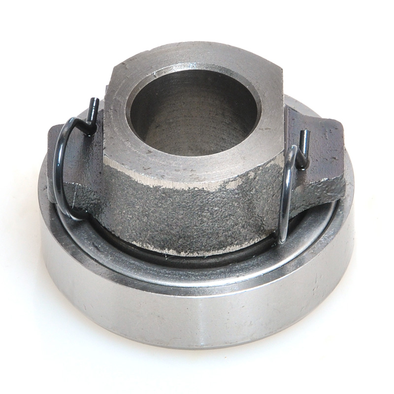
Plain Bearings (Bushings and Sleeve Bearings)
Plain bearings have no rolling elements. A shaft (journal) rotates inside a bearing surface, with a lubricant film separating the two. They are simpler, quieter, and more compact than rolling-element bearings and can handle very heavy loads and shock loads well. Bronze, babbitt, and PTFE-lined variants are common material choices. Agriculture, marine applications, and construction equipment use plain bearings widely. The gudgeon pin connecting a piston to a connecting rod in a diesel engine is a classic plain bearing application. Maintenance requirements are higher than sealed rolling-element bearings because the lubricant film must be maintained continuously.
Fluid and Magnetic Bearings
Fluid bearings support loads on a thin pressurized layer of oil, water, or air rather than direct contact surfaces. They achieve near-zero friction and exceptional vibration damping, making them suitable for precision equipment like large turbines, machine tool spindles, and MRI machines. Magnetic bearings use electromagnetic or permanent magnetic forces to levitate the shaft entirely, eliminating contact and friction. Active magnetic bearings include sensor-controlled electromagnets that continuously adjust position. These technologies are sophisticated and expensive but deliver lifespan and performance that no contact bearing can match in critical applications.
How to Select the Right Bearing for Any Application
Selecting the wrong bearing is one of the most common sources of premature failure and unnecessary maintenance costs. The selection process requires evaluating several factors together, not in isolation.
| Selection Factor | Condition | Recommended Bearing Type |
|---|---|---|
| Load direction | Pure radial | Cylindrical roller bearing |
| Load direction | Pure axial | Thrust ball or roller bearing |
| Load direction | Combined radial + axial | Angular contact or tapered roller |
| Speed | High speed (>10,000 rpm) | Deep groove ball, angular contact ball |
| Speed | Low speed, heavy load | Spherical or tapered roller bearing |
| Misalignment | Shaft deflection or housing flex | Spherical roller or self-aligning ball |
| Space constraints | Very limited radial space | Needle roller bearing |
| Noise/vibration | Precision quiet operation required | Deep groove ball, fluid, or magnetic |
Load Type and Magnitude
The first question in any bearing selection process is the direction and size of the load. Radial loads act perpendicular to the shaft; axial (thrust) loads act along its length. Most real applications involve some combination of both. For purely radial loads, cylindrical roller bearings offer maximum capacity per unit of cross-section. For heavy combined loads, tapered roller or spherical roller bearings are the standard industry choice. Shock loads — sudden impacts or impulse forces — demand bearings with higher internal clearance and more robust materials, typically roller bearings rather than ball bearings.
Rotational Speed
Every bearing has a published speed rating expressed in rpm. Exceeding this limit generates heat, accelerates lubricant degradation, and causes rapid wear. Ball bearings generally achieve higher speed ratings than roller bearings of the same bore size because the smaller contact area between ball and raceway generates less friction heat. Deep groove ball bearings and angular contact ball bearings are the standard for high-speed work. At the other extreme, very low-speed heavy applications — such as slow-rotating conveyor rollers carrying high loads — perform best with spherical or cylindrical roller designs that provide adequate lubrication film formation even at low surface speeds.
Misalignment Tolerance
In an ideal machine, the shaft and housing are perfectly aligned. In reality, manufacturing tolerances, thermal expansion, structural flex under load, and installation errors all introduce some degree of misalignment. Most rolling-element bearings tolerate only tiny amounts of misalignment — often under 0.1° — before edge loading causes localized stress and accelerated fatigue. Where misalignment is expected or unavoidable, self-aligning ball bearings and spherical roller bearings are the engineered solution. Their outer ring geometry accommodates shaft angular deflection while distributing load evenly across the rolling elements.
Operating Environment
Temperature, contamination, moisture, and chemical exposure all influence bearing selection. Standard bearing steel begins to lose hardness above approximately 120°C. High-temperature applications require bearings made from specially stabilized steel, ceramic materials, or with high-temperature grease formulations. Stainless steel bearings resist corrosion in wet or mildly corrosive environments. Full ceramic or ceramic hybrid bearings (steel rings with ceramic rolling elements) handle corrosive chemicals, high temperatures, and electrically isolated applications — such as motors with variable frequency drives, where electrical current passing through standard steel bearings causes pitting damage to raceways.
Bearing Lubrication: The Factor That Controls 80% of Service Life
Research consistently shows that nearly 80% of bearing failures are linked to lubrication-related issues — wrong lubricant type, wrong quantity, contaminated lubricant, or lubrication intervals that are too long. Getting lubrication right is the single highest-leverage maintenance action for bearing longevity.
Grease vs. Oil: Choosing the Right Medium
Grease is the dominant lubricant for most rolling-element bearing applications. It stays in place without a sealed housing, provides some sealing effect against contamination ingress, and requires less frequent reapplication than oil. Lithium-based greases cover the majority of general industrial applications. Polyurea-based greases perform well at high speeds and resist water contamination, making them common in electric motors. For extreme temperatures, specialty greases based on synthetic base oils — such as PAO or ester oils — maintain performance where mineral oil-based products would degrade or solidify.
Oil lubrication is used when heat dissipation is critical, when very high speeds demand lower viscosity than any grease can provide, or when a circulating system is already present in the machine. Turbine bearings, high-speed spindle bearings, and gearbox bearings commonly use oil. The key principle: viscosity must match operating speed and load. High-speed applications need low-viscosity oils to minimize churning losses and heat generation; heavy-load, low-speed bearings need higher viscosity to maintain the protective film under pressure.
How Much Lubricant Is Correct
Both under-lubrication and over-lubrication damage bearings, though for different reasons. Under-lubricated bearings run on metal-to-metal contact, generating heat and causing adhesive wear almost immediately. Over-lubricated bearings — a common mistake in grease-packed applications — churn the excess grease, generating heat through viscous drag that can be as damaging as insufficient lubrication. For most grease-lubricated rolling-element bearings, filling the bearing housing to approximately one-third to one-half capacity is the standard recommendation. Always consult the manufacturer's specification for the specific bearing and housing combination.
Re-lubrication Intervals
Grease does not last forever. Base oil bleeds out over time, thickener degrades, and contaminants accumulate. For general industrial bearings running at moderate speeds and loads in normal environments, re-lubrication every 3 to 6 months is a typical starting point. Bearings operating at high speeds, elevated temperatures, under heavy loads, or in contaminated environments require more frequent attention — potentially monthly or even weekly in extreme conditions. Automated lubrication systems that deliver small, precise quantities of fresh grease continuously are increasingly common in heavy industry because they maintain optimal film conditions without the labor cost of manual re-lubrication rounds.
Bearing Failure: The Four Stages and What Causes Them
Bearing failure rarely happens without warning. There is a well-documented progression through four stages, and recognizing the signs at each stage determines whether a bearing is replaced on a planned schedule or causes an unexpected breakdown that takes the entire machine offline.
Stage 1 — Early Subsurface Defects
In the first stage, small subsurface defects develop in the raceways or rolling elements as fatigue cycles accumulate. These defects appear at ultrasonic frequencies, typically in the 20,000–60,000 Hz range, detectable only with specialized ultrasonic monitoring equipment or high-frequency vibration sensors. The bearing is still functioning within normal parameters. At this stage, the most likely cause is inadequate lubrication film — a gap between raceway and rolling element allows micro-contact. No immediate replacement is required, but the lubrication regime should be reviewed.
Stage 2 — Defects Ring at Natural Frequencies
As defects grow, they begin exciting the natural resonance frequencies of the bearing components, ranging from approximately 500 to 2,000 Hz. This is detectable with standard vibration analysis equipment. Bearing defect frequencies — BPFO (ball pass frequency outer race), BPFI (ball pass frequency inner race), BSF (ball spin frequency), and FTF (fundamental train frequency) — appear in the vibration spectrum. At Stage 2, replacement should be planned within weeks, not months. Continued operation is acceptable with regular monitoring, but the window for planned intervention is closing.
Stage 3 — Visible Damage and Rising Temperature
Stage 3 brings visible damage to raceways and rolling elements — pitting, spalling, and surface fatigue. Vibration amplitudes increase significantly. Heat generation rises noticeably. Audible noise may develop, ranging from a low rumble to high-pitched squealing depending on the failure mode. At this point, replacement is urgent. Continuing to run a Stage 3 bearing risks progression to complete failure within hours or days rather than weeks.
Stage 4 — Imminent Catastrophic Failure
In Stage 4, the vibration noise floor rises broadly across all frequencies as the bearing structure disintegrates. Paradoxically, the sharp defect-frequency peaks that were visible in Stage 2 and 3 may actually decrease as the signal becomes broadband noise — a counterintuitive but critical sign that the bearing is seconds or minutes from total collapse. Immediate shutdown and replacement are the only options. A Stage 4 bearing that fails in service can damage the shaft, housing, adjacent components, and connected machinery, turning a bearing replacement into a major repair.
Root Causes Behind Most Bearing Failures
The five root causes that account for the vast majority of bearing failures are:
- Lubrication problems — wrong type, wrong quantity, contaminated, or degraded lubricant
- Improper installation — excessive force on the wrong ring, incorrect fit, or inadequate preload adjustment
- Misalignment — shaft or housing alignment errors that cause uneven load distribution
- Contamination — particles, moisture, or chemicals entering the bearing through damaged or inadequate seals
- Electrical discharge — stray currents from VFDs or improper grounding passing through bearing rolling contacts and causing raceway pitting
Each of these causes is entirely preventable with correct specification, careful installation, and a disciplined maintenance program.
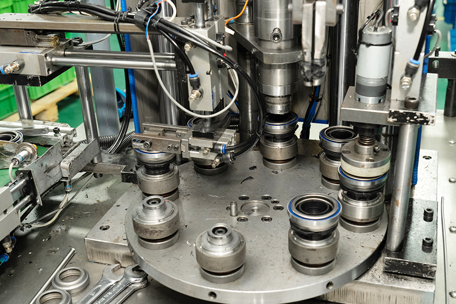
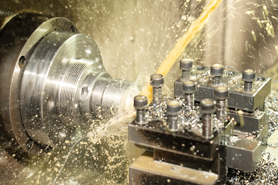
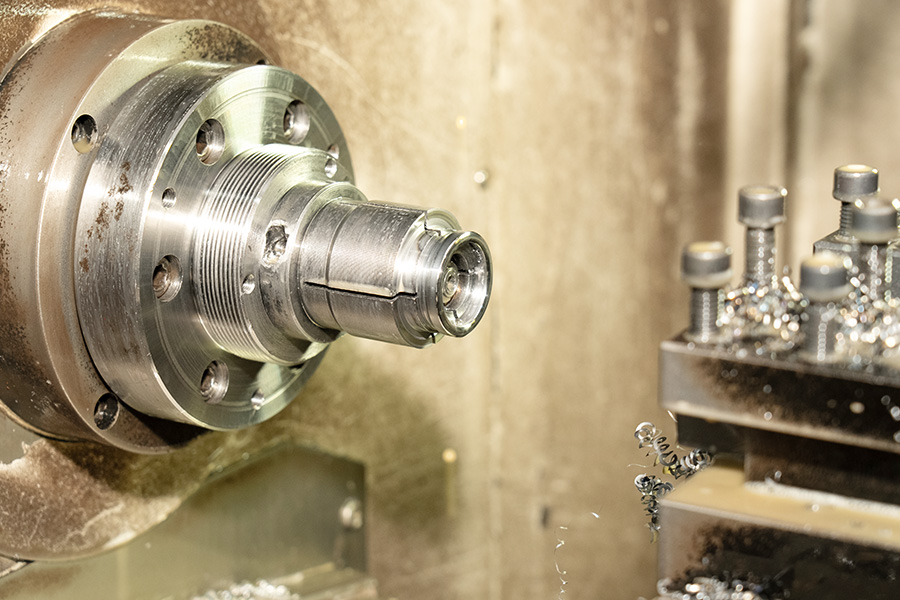
Bearing Installation: Where Most Preventable Failures Begin
A bearing that is installed incorrectly will fail before it comes close to its rated service life, regardless of quality. Correct installation requires the right tools, the right technique, and careful attention to fit tolerances.
Press Fitting and Mounting Force
The most fundamental rule of bearing installation: mounting force must be applied only to the ring being fitted. When pressing a bearing onto a shaft, force must go through the inner ring only — never through the rolling elements and outer ring. Forcing the outer ring during inner ring mounting passes the full press force through the balls or rollers, creating Brinell indentations (dents) in the raceways that cause vibration and premature fatigue. The correct tools are sleeve drivers that contact only the target ring face, induction heaters that expand the bearing for an interference fit without force, or hydraulic oil injection for large diameter bearings.
Shaft and Housing Fit Tolerances
Bearing rings must be correctly fitted to their mating components. A rotating ring that carries load — typically the inner ring on a shaft — requires an interference fit to prevent creep (slipping on the shaft surface under load). A stationary ring — typically the outer ring in a fixed housing — can use a lighter, sliding fit that allows slight axial displacement for thermal expansion. Incorrect fits cause fretting corrosion on shaft and housing bores, which looks like fine reddish-brown powder around the bearing seat and indicates the ring is moving where it should not.
Preload and Internal Clearance
Internal clearance refers to the free movement of rolling elements within a bearing before it is loaded. Standard bearings are manufactured with normal clearance (CN). High-speed applications often need reduced clearance (C2) to limit ball or roller excursion at speed and reduce vibration. High-temperature applications or assemblies with heavy interference fits need increased clearance (C3 or C4) to compensate for thermal expansion that would otherwise eliminate clearance and cause preloading. For paired bearing arrangements — back-to-back or face-to-face angular contact or tapered roller sets — the preload must be set precisely per the manufacturer's specification. Too little preload causes the bearings to chatter; too much causes overheating and rapid fatigue.
Bearing Materials and Coatings: Matching Construction to Conditions
The performance of any bearing is only as good as its material properties under the specific conditions it faces. Standard through-hardened bearing steel covers the vast majority of industrial applications, but specialized materials and surface treatments open the door to applications where standard steel would fail quickly.
Standard Bearing Steel
The overwhelming majority of rolling-element bearings use high-carbon chromium bearing steel — typically grades like 52100 — that is through-hardened to 58–65 HRC. This material offers an excellent combination of hardness, toughness, and fatigue resistance. Its practical temperature limit is approximately 120°C for standard grades. Above that threshold, the steel undergoes dimensional changes as retained austenite transforms, causing the bearing to lose its precision fits.
Ceramic and Hybrid Bearings
Silicon nitride (Si₃N₄) ceramic is the dominant ceramic material in precision bearing applications. Hybrid bearings use ceramic rolling elements with steel rings, offering a compelling combination of properties: 60% lower density than steel (reducing centrifugal loading at high speed), 50% higher hardness (improving surface fatigue resistance), electrical insulation (essential for VFD motor applications), and operating temperatures up to 800°C in full ceramic configurations. Hybrid bearings are standard in high-speed machine tool spindles, electric vehicle motors, and semiconductor manufacturing equipment where contamination by metallic wear particles is unacceptable.
Stainless Steel and Coated Bearings
Martensitic stainless steel bearings resist corrosion in moist, lightly acidic, or food-grade environments at the cost of some hardness and fatigue life compared to standard steel. For more aggressive chemical environments, black oxide, phosphate, and DLC (diamond-like carbon) coatings extend the corrosion resistance of standard steel bearings without the full cost of a stainless grade. DLC coatings also improve wear resistance in boundary lubrication conditions — situations where a full lubricant film cannot form because speeds are too low or loads too high.
Bearing Condition Monitoring: Moving from Reactive to Predictive Maintenance
The economics of bearing maintenance have shifted dramatically over the past two decades. Replacing bearings reactively — waiting until failure — means unplanned downtime, potential cascading damage, and emergency labor costs. Replacing them preventively on a fixed schedule means replacing many bearings that still had significant useful life remaining. Predictive maintenance based on condition monitoring lets you replace bearings when they actually need it, not before and not after.
Vibration Analysis
Vibration analysis is the primary tool for bearing condition monitoring. Accelerometers mounted on bearing housings capture the vibration signature of the rotating assembly. Time waveform analysis, FFT spectrum analysis, and envelope (demodulation) analysis each extract different information. Envelope analysis is particularly powerful for early-stage bearing defects because it extracts bearing defect frequencies that are often buried in the background noise of broader machine vibration. Advanced algorithms can provide 6 to 24 months of advance warning from the earliest Stage 1 defects to the point where replacement is necessary — time enough to schedule maintenance in the next planned shutdown rather than responding to an emergency.
Temperature Monitoring
A bearing that is failing generates heat. Temperature sensors or periodic infrared thermography can detect abnormal heat buildup before it reaches destructive levels. The practical limitation is that temperature is a relatively late indicator — it typically rises significantly only at Stage 3 of the failure progression, when vibration analysis would already have provided an earlier warning. Temperature monitoring is most useful as a complementary check, particularly on bearings in inaccessible locations where vibration sensors are not installed.
Ultrasonic Monitoring
Ultrasonic monitoring detects the high-frequency acoustic emissions produced by early subsurface defects and lubrication film breakdown in the 20,000–60,000 Hz range. It is the earliest detection method available, capable of identifying inadequate lubrication before any visible damage has occurred. Portable ultrasonic instruments are widely used for route-based lubrication programs — the technician listens to the bearing before and after greasing, confirming when sufficient lubricant has been added without over-packing the housing.
Bearing Applications Across Industries: From Automotive to Aerospace
Bearings appear in virtually every industry and nearly every mechanical device. Understanding how each sector uses bearings differently sharpens the judgment needed for application-specific selection and maintenance decisions.
Automotive Bearings
A modern passenger vehicle contains dozens of bearings. Wheel bearings — typically double-row angular contact or tapered roller units in sealed hub assemblies — carry both radial load from the vehicle weight and axial loads from cornering forces while rotating at road speed for the life of the vehicle without regreasing. Gearbox shafts use needle roller and tapered roller combinations. Engine crankshafts run on hydrodynamic plain bearings (engine bearings) that form an oil film at operating speed. Alternators, power steering pumps, and air conditioning compressors each use their own specialized bearing arrangements.
Industrial and Manufacturing Bearings
Heavy industrial equipment — rolling mills, crushers, conveyors, pumps, fans, and compressors — represents the highest demand end of bearing applications. Spherical roller bearings dominate where heavy loads and shaft deflection coexist. Large-diameter slewing ring bearings allow excavators, cranes, and wind turbine nacelles to rotate. Conveyor idler rollers run on simple ball bearing cartridges designed for long greased intervals with minimal maintenance attention. Paper mills and steel plants operate in contaminated, wet, high-load environments where sealed bearings with heavy-duty grease formulations are essential.
Aerospace Bearings
Aerospace applications impose the most stringent requirements of any bearing category — extreme temperatures, high speeds, wide load ranges, minimal weight, and absolute reliability. Jet engine main shaft bearings run at surface speeds exceeding 3 million DN (bore diameter in mm × rpm) under combined thermal and mechanical loads. Hybrid ceramic bearings with M50 tool steel rings and silicon nitride rollers are the standard for these positions. Flight control surface actuators use high-precision angular contact ball bearings. Helicopter rotor head bearings operate under combined oscillating loads and must be absolutely reliable under all flight conditions. Every aerospace bearing is subject to material traceability requirements and defined inspection intervals that do not exist in most industrial applications.
Wind Energy Bearings
Wind turbines present a unique set of bearing challenges. The main shaft bearing carries very high radial loads from the rotor weight and variable axial loads from wind thrust, often in a highly contaminated environment inside a nacelle that is difficult to access for maintenance. Gearbox bearing failures have historically been one of the leading causes of wind turbine downtime, driving the industry toward direct-drive designs that eliminate the gearbox and its bearings entirely, or toward longer-life, heavily monitored bearing arrangements with online condition monitoring as standard equipment.
Practical Bearing Maintenance Checklist for Industrial Equipment
A structured maintenance approach covers the full lifecycle of a bearing — from storage and installation through monitoring and eventual replacement. The following practices apply to most rolling-element bearing applications in industrial settings.
Storage and Handling
Bearings should remain in their original packaging until installation. They are precision components machined to tolerances measured in micrometers; any contamination or mechanical damage during storage directly reduces service life. Store bearings horizontally in a dry, vibration-free environment at consistent temperature. Never use compressed air to spin a bearing — the rolling elements can exceed safe speed limits without the bearing being loaded, and the air stream carries contaminants that embed in the raceway surfaces.
Installation Checklist
- Verify shaft and housing dimensions against the bearing specification before installation
- Clean all mating surfaces thoroughly and inspect for burrs, scratches, or corrosion
- Use an induction heater or oven to heat interference-fit inner rings to 80–90°C for fitting — never use a direct flame
- Apply mounting force only to the ring being fitted, never through the rolling elements
- Verify internal clearance or preload after installation per manufacturer specification
- Fill with the correct grease type and quantity before startup
- Run in at reduced load and speed to allow the lubricant to distribute and temperature to stabilize
Ongoing Monitoring and Maintenance
- Establish a documented re-lubrication schedule based on operating conditions, not a generic calendar interval
- Conduct periodic vibration measurements and trend the data — a single reading tells you little; trends reveal deterioration
- Check bearing temperature during operation; sudden increases of more than 10–15°C above normal running temperature indicate a problem
- Inspect seals during maintenance shutdowns for wear, damage, or contamination ingress
- When replacing a failed bearing, always analyze the removed bearing to identify the failure root cause — replacing without addressing the cause will repeat the failure
- Keep records of bearing replacements, lubricant types, and vibration readings to build a maintenance history for each machine
Related Products
Contact Us
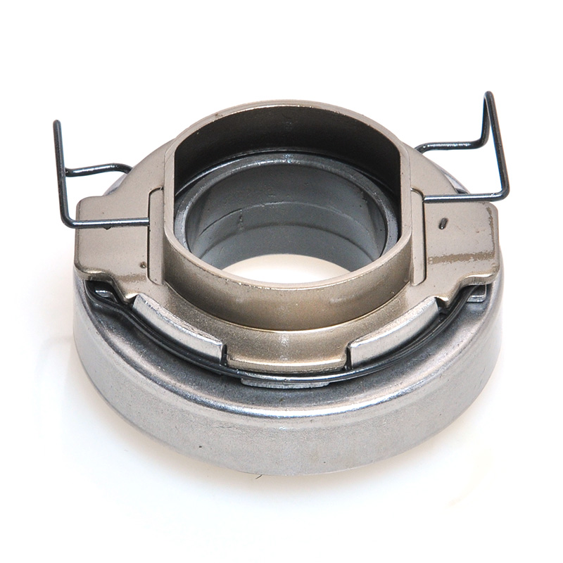
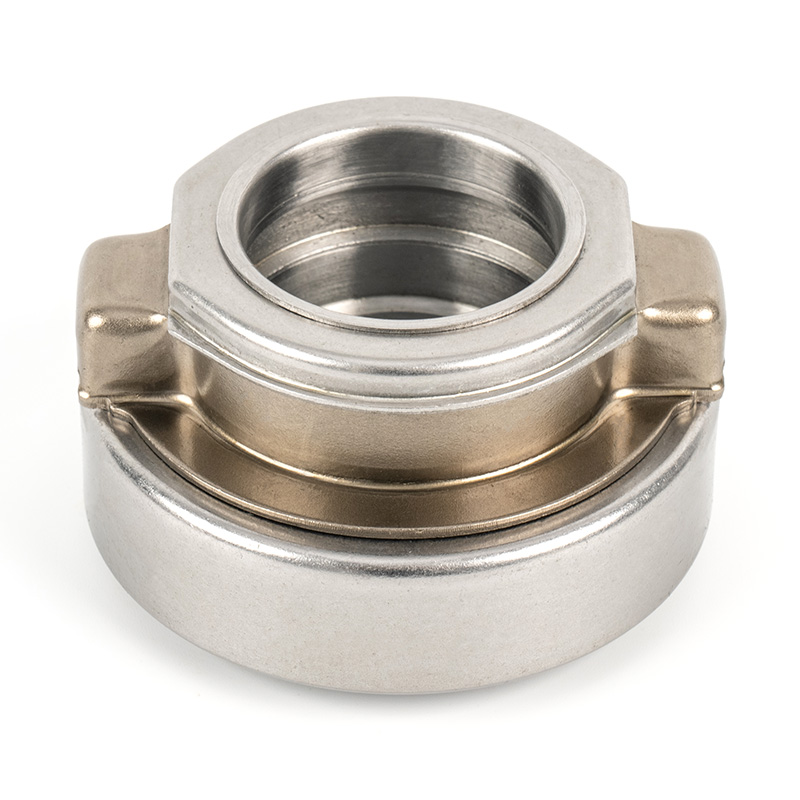
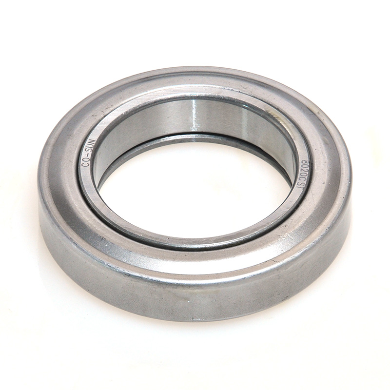
A production enterprise specializing in the production of automobile clutch bearings and other non-standard bearings.
- Contact Information
-
 +86-575-86013311
 -
 +86-575-86013322
 -
 No. 50, Tashan 1st Road, Xinchang County, Shaoxing, Zhejiang, China
Copyrigh t© Xinchang Heyang Auto Parts Co., Ltd.. All Rights Reserved.
China auto bearing manufacturers wholesale auto bearing supplier
