 +86-13867573512
 [email protected]
 Get a quote

 English
  Español
Drive Bearing Guide: Types, Failure Causes & Maintenance
Author: Heyang Date: Jul 06, 2026
Content
- 1 What a Drive Bearing Does and Why It Fails Faster Than People Expect
- 2 Main Types of Drive Bearings and Where Each One Fits
- 3 Radial Load vs Axial Load: Why Drive Bearing Selection Depends on Both
- 4 Sealing Options: Open, Shielded, and Sealed Drive Bearings
- 5 Shaft and Housing Fit: Getting the Tolerance Right
- 6 Common Causes of Drive Bearing Failure
- 7 How Drive Bearings Are Installed: Mounting Methods Explained
- 8 Early Warning Signs a Drive Bearing Is Failing
- 9 Lubrication and Maintenance Practices That Extend Drive Bearing Life
- 10 Drive Bearings Across Industries
- 11 How to Choose the Right Drive Bearing for Your Application
- 12 Glossary of Key Drive Bearing Terms
- 13 Frequently Asked Questions About Drive Bearings
- 13.1 What is the difference between a drive bearing and a regular support bearing?
- 13.2 How long does a drive bearing typically last?
- 13.3 Can a drive bearing fail even if it is well lubricated?
- 13.4 What noise does a failing drive bearing usually make?
- 13.5 Is a tapered roller bearing always the right choice for a drive shaft?
- 13.6 How often should a drive bearing be relubricated?
- 13.7 What is the most common root cause of drive bearing failure?
- 13.8 Should a drive bearing be sealed or shielded?
- 13.9 What is the safest way to mount a drive bearing onto a shaft?
- 13.10 Why do drive bearings fail more often in electric motor applications?
What a Drive Bearing Does and Why It Fails Faster Than People Expect
A drive bearing is the rolling-element bearing mounted inside a drive shaft, gearbox, or transmission housing that supports a rotating shaft while carrying both radial and axial loads generated during power transmission. Unlike a simple support bearing, a drive bearing typically works under combined loading, higher rotational speed, and more heat than a standard bearing in the same machine, which is why its selection, installation, and maintenance schedule usually need to be stricter than the rest of the driveline.
In practice, the term covers several rolling-element families - tapered roller bearings, cylindrical roller bearings, spherical roller bearings, deep groove ball bearings, and needle roller bearings - each suited to a different combination of load direction, speed, and available space. Beyond the rolling element itself, a working drive bearing assembly also depends on the right shaft and housing fit, the correct sealing arrangement, and a lubrication routine matched to the application. Get any one of those wrong and the bearing type on the label stops mattering, because the failure mode shifts from fatigue at the end of a long service life to premature wear within weeks or months.
The sections below walk through how to tell drive bearing types apart, how radial and axial load shape that decision, what actually causes a drive bearing to fail early, the sealing and fit choices that protect it, how it gets installed correctly, where each type shows up across different industries, and the maintenance habits that reliably extend service life in real operating conditions.
2 Load directions a drive bearing must resist: radial and axial
5 Common bearing types used across drive shaft and gearbox designs
1 in 6 Premature bearing failures traced back to poor fitting practice alone
Main Types of Drive Bearings and Where Each One Fits
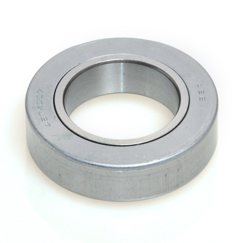
Drive bearing selection starts with the shape of the rolling element, because geometry determines how much radial load, axial load, or combined load the bearing can absorb without premature fatigue. The five types below cover the large majority of drive shaft, gearbox, and transmission applications found in automotive, industrial, and heavy-machinery equipment.
Tapered Roller Bearings
Conical rollers running on conical raceways let this bearing carry radial and axial loads at the same time, which is why it shows up constantly in wheel hubs, differentials, and main drive systems where the shaft pushes both sideways and along its axis. Tapered roller bearings are frequently mounted in matched pairs, back to back or face to face, so the assembly can resist thrust from either direction.
Cylindrical Roller Bearings
Line contact between the rollers and the raceway spreads radial load over a wide surface, giving this bearing a strong radial capacity. It is a common choice in industrial gear reducers, paper machinery, and railway drive units carrying heavy pure-radial loads, though most designs need a separate thrust bearing if axial load is also present.
Spherical Roller Bearings
Barrel-shaped rollers give this bearing a built-in self-aligning ability, so it tolerates shaft deflection and housing misalignment better than most other drive bearing types. Wind turbine main shafts, mining crushers, and heavy gearboxes rely on this tolerance, since long shafts in these machines rarely stay perfectly straight under load.
Deep Groove Ball Bearings
Spherical balls set in a deep-groove race handle moderate radial and axial loads with low friction and quiet running. This makes them a practical fit for smaller drive shafts, pumps, and motor-driven shafts that do not see extreme loading, and their simple design keeps replacement cost and lead time low.
Needle Roller Bearings
Thin, elongated rollers pack more rolling elements into a small cross-section, which is exactly why this bearing is chosen when radial space is tight, such as gearbox shafts and connecting rod journals in compact drivetrains. The trade-off is a lower axial load capacity than a tapered or spherical roller design.
Radial Load vs Axial Load: Why Drive Bearing Selection Depends on Both
Every drive bearing decision comes back to a simple question: which direction is the load actually pushing? A radial load presses perpendicular to the shaft, the way a conveyor roller is pressed down by the weight of material sitting on the belt. An axial load, often called thrust, pushes along the same direction as the shaft itself, the way gears exert force along a transmission shaft as they shift and engage.
Radial Load
- Acts perpendicular to the shaft axis
- Typical source: shaft weight, belt tension, gear meshing force
- Well handled by cylindrical roller and deep groove ball bearings
- Dominant load type in conveyor rollers and pump shafts
Axial Load (Thrust)
- Acts along the shaft axis
- Typical source: gear shifting, propeller thrust, vertical shaft weight
- Well handled by tapered roller and thrust ball bearings
- Dominant load type in wheel hubs and vertical pump shafts
Many drive shafts see radial and axial load at the same time, which is exactly why tapered roller bearings are so common in this position - the conical geometry lets one bearing do the work that would otherwise need two separate bearing types stacked together. When a drive bearing is undersized for either load direction, the rolling elements skid instead of rolling cleanly, and that skidding is where a large share of early bearing wear actually starts.
Sealing Options: Open, Shielded, and Sealed Drive Bearings
Once the rolling-element type is chosen, the next decision is how the drive bearing is enclosed, because sealing controls how well it resists contamination and how much friction it adds to the system. There are three broad categories, and the right one depends on cleanliness, speed, and how easily the bearing can be serviced later.
| Enclosure Type | Contamination Protection | Friction / Speed | Typical Use |
|---|---|---|---|
| Open (no shield or seal) | None on its own | Lowest friction, highest speed | Oil-bathed gearboxes and clean enclosed housings |
| Shielded (non-contact metal) | Moderate, blocks larger particles only | Low friction, high speed | Electric motors, fans, moderately clean environments |
| Sealed (rubber contact seal) | Highest, blocks dust and moisture | Higher friction, reduced top speed | Washdown, outdoor, and hard-to-service positions |
Open drive bearings rely entirely on the surrounding housing to keep contaminants out, so they only make sense inside a clean, continuously oil-fed gearbox. Shielded bearings add a non-contact metal barrier that keeps out coarse debris while barely touching running friction, which is why they are common in general-purpose motors. Sealed drive bearings press a rubber lip against the inner ring, which sacrifices some speed capacity and adds a small amount of heat but gives the best protection in dirty, wet, or outdoor drive shaft applications where frequent service is impractical.
Shaft and Housing Fit: Getting the Tolerance Right
A drive bearing that is perfectly selected on paper can still fail early if the shaft and housing tolerances around it are wrong. Fit is not a single setting - it is chosen based on which ring rotates, how heavy the load is, and whether the housing needs to be removed for service.
Interference (tight) fit
Used on the rotating ring, most often the shaft, to stop the bearing from creeping or spinning under load. Heavier loads call for more interference, but excessive interference reduces internal clearance and raises operating temperature.
Clearance (loose) fit
Used on the stationary ring, typically the housing, to allow for easy assembly, thermal expansion, and disassembly during service without disturbing the rotating fit.
Transition fit
A middle-ground fit applied where some adjustment or easier removal is needed, commonly used on housing bores in general industrial drive bearing installations.
Why fit errors matter
A fit that is too loose lets the bearing creep and generate heat from internal spinning; a fit that is too tight removes internal clearance and can crack the raceway under normal load.
As a working rule, most general drive shaft applications with a rotating inner ring and a steady radial load call for an interference fit on the shaft and a transition or clearance fit in the housing. Applications with an axially split housing typically use a looser housing fit specifically to avoid distorting the outer ring when the housing halves are bolted together.
Common Causes of Drive Bearing Failure
Bearing engineers who investigate premature failures consistently point to the same handful of root causes, and lubrication problems sit at the top of that list more often than any mechanical defect in the bearing itself. Roughly half of all rotating-machine bearing failures trace back to inadequate lubrication, contamination, or misalignment rather than a manufacturing flaw, which means most drive bearing failures are preventable with better operating practices rather than a different bearing.
- Lubrication starvation or breakdown - insufficient grease, degraded oil, or the wrong viscosity for the operating temperature leaves rolling elements running in direct metal-to-metal contact.
- Over-greasing - packing a bearing housing with more grease than the design calls for traps heat, which softens the thickener and blocks the thin oil film the rolling elements actually depend on.
- Contamination - dirt, metal shavings, or moisture entering through a worn seal act like an abrasive, grinding away the raceway surface with every rotation.
- Misalignment - a shaft or housing that is out of true forces the rolling elements to carry uneven load across the raceway, concentrating wear on one edge instead of spreading it evenly.
- Overload - running a drive bearing beyond its rated radial or axial capacity accelerates fatigue and shortens service life even when lubrication and alignment are otherwise correct.
- Improper installation - forcing a bearing onto a shaft with the wrong fit, striking the wrong ring during mounting, or skipping lubrication at assembly can create damage that only shows up after weeks of running.
- Incorrect shaft or housing fit - a fit that is looser or tighter than specified changes internal clearance and can lead to creeping, overheating, or raceway cracking well before the bearing reaches its rated fatigue life.
How Drive Bearings Are Installed: Mounting Methods Explained
Installation quality is just as decisive as bearing selection, since force applied to the wrong ring or an out-of-tolerance shaft can damage a brand-new bearing before it ever runs. Three mounting methods cover almost every drive bearing installation, and the right one depends mainly on bearing size.
Mechanical (cold) mounting
Used for smaller bearings, force is applied through the ring being fitted using a press or a sleeve and impact ring, never through the rolling elements. This is the most common method for bearings up to roughly four inches in bore diameter.
Shrink (hot) mounting
The bearing is heated with an induction heater so it expands enough to slide onto the shaft without excessive force, then cools and shrinks into a tight fit. Manufacturers typically cap heating temperature well under the point that could affect the bearing's heat treatment.
Hydraulic mounting
Reserved for the largest drive bearings, a hydraulic press or an adapter sleeve with a hydraulic nut distributes mounting force evenly and avoids the risk of shock loading that a hammer-driven method would create at that size.
Pre-installation checks
Measure the shaft and housing bore against the specified tolerance before mounting, inspect for nicks or burrs, and keep the bearing in its packaging until the moment of installation to prevent contamination from settling on the raceway.
During and after mounting
Force should always drive through the ring with the interference fit, never through the balls, rollers, or the opposite ring, and the assembly should be seated firmly against the shaft shoulder to eliminate any axial gap before the bearing is put into service.

Early Warning Signs a Drive Bearing Is Failing
Catching a failing drive bearing early is almost always cheaper than replacing it after a seizure, because early symptoms are usually limited to the bearing itself while a full seizure can damage the shaft, housing, and surrounding gears. The table below summarizes the signs most often reported during routine inspection and what they typically point to.
| Observed Sign | Likely Cause |
|---|---|
| Rising operating temperature | Insufficient or breaking-down lubricant |
| Grinding or rumbling noise | Contamination or surface pitting on the raceway |
| Burnt lubricant smell | Extended running at elevated temperature |
| Blue or brown discoloration on the outer ring | Prolonged heat exposure that has already reduced hardness |
| Visible vibration or shaft wobble | Misalignment or raceway fatigue |
| Dropping oil pressure in a lubricated housing | Worn bearing clearance allowing oil to bypass |
| Grease that has become inconsistent or gritty | Wrong grease viscosity for the operating speed and heat |
Vibration and temperature monitoring are now common on higher-value drive shafts precisely because these two readings tend to trend upward well before a bearing produces an audible noise, giving maintenance teams a window to schedule replacement rather than react to a breakdown.
Lubrication and Maintenance Practices That Extend Drive Bearing Life
Most of the maintenance work that actually extends drive bearing life happens before a problem is visible, through a handful of consistent habits rather than a single corrective action.
Set a documented relubrication interval
Base the interval on operating speed, load, and temperature rather than a generic calendar date, then adjust it using inspection data such as temperature and vibration trends over time.
Use the correct lubricant quantity
A bearing only lubricates itself with the thin oil film that bleeds from the grease at the rolling contact zones, so adding more grease than the housing needs simply traps heat instead of improving lubrication.
Protect against contamination
Keep seals in good condition, filter grease and oil where possible, and control the cleanliness of the area around the bearing housing during any maintenance work.
Verify alignment and mounting fit at every service
Check shaft and housing fits against the manufacturer specification, and confirm mounting practice each time a drive bearing is installed or reinstalled after service.
Track temperature and vibration trends
A gradual rise in either reading over weeks is usually a more reliable early indicator than any single reading taken in isolation.
Keep replacement bearings sealed until installation
A bearing left unpacked on a workbench collects dust and moisture before it ever turns a single revolution, so open the packaging only at the moment of mounting.
Drive Bearings Across Industries
The same core bearing types get selected differently once real operating conditions - load, speed, contamination, and duty cycle - are factored in for a specific industry. The examples below show how the same engineering principles play out in different equipment.
Automotive Drivetrains
Wheel hubs and differentials favor tapered roller bearings for their combined radial and axial capacity, while smaller shafts in alternators and water pumps typically use deep groove ball bearings for their compact size and low friction.
Wind Energy
Main shaft bearings on wind turbines lean on spherical roller bearings for their self-aligning tolerance, since long shafts operating outdoors under variable wind loading rarely maintain perfect alignment over years of service.
Material Handling and Conveyors
Conveyor rollers and idlers mostly see steady radial load, so cylindrical roller or deep groove ball bearings are the standard choice, often paired with sealed enclosures where dust or outdoor exposure is a factor.
Agricultural Machinery
Drive shafts on tillers, harvesters, and balers run in dusty, wet field conditions, which pushes selection toward sealed bearings and tapered roller designs that tolerate both contamination risk and combined loading.
Marine and Propulsion Shafts
Propeller shaft thrust makes axial load the dominant factor, so tapered roller or dedicated thrust bearings are typical, usually specified with corrosion-resistant materials or coatings for salt-water exposure.
How to Choose the Right Drive Bearing for Your Application
Selecting a drive bearing comes down to matching bearing geometry, sizing, sealing, and fit to the actual operating conditions of the shaft it will support. The checklist below covers the factors that most often decide whether a bearing choice lasts for years or needs early replacement.
Load direction and magnitude
Confirm whether the shaft applies radial load, axial load, or both, and size the bearing to the higher of its rated capacities rather than an average expectation.
Operating speed
High-speed shafts favor ball bearings and lighter roller designs, while lower-speed, heavier-load shafts favor larger roller bearings such as spherical or tapered roller types.
Operating temperature range
Match grease type and bearing clearance class to the expected temperature range, since standard grease breaks down faster in consistently hot environments.
Shaft and housing fit
Confirm the tolerance class specified for the shaft and housing bore, since an incorrect fit is one of the more common causes of early bearing wear.
Sealing requirement
Choose a sealed or shielded bearing where contamination from dust, moisture, or debris is a realistic risk in the operating environment.
Available radial space
Where housing space is limited, needle roller bearings often fit where a standard roller bearing of equal capacity would not.
Installation and service access
A drive bearing in a hard-to-reach location favors a sealed, low-maintenance design, while an easily serviced position can rely on more frequent relubrication instead.
Duty cycle and downtime cost
Continuous-duty equipment with high downtime cost justifies a more conservative bearing rating and shorter inspection interval than intermittent-duty equipment.
Glossary of Key Drive Bearing Terms
Radial load
Force acting perpendicular to the shaft axis.
Axial load (thrust)
Force acting along the shaft axis rather than across it.
Interference fit
A fit where the bearing bore is slightly smaller than the shaft, or the outer ring slightly larger than the housing bore, creating a tight mechanical grip.
Clearance fit
A fit that leaves a small gap between the bearing and its mating part, allowing easier assembly and disassembly.
Preload
An intentional internal load applied during assembly, often in tapered roller bearing pairs, to remove internal clearance and improve stiffness.
Raceway
The hardened surface on the inner or outer ring on which the rolling elements travel.
Cage
The component that spaces the rolling elements evenly around the raceway and keeps them from contacting each other.
Fluting
Washboard-like damage on the raceway caused by electrical current passing through the bearing, common in motor-driven shafts.
Frequently Asked Questions About Drive Bearings
What is the difference between a drive bearing and a regular support bearing?
A drive bearing sits within the power-transmission path of a shaft, gearbox, or differential and is expected to carry combined radial and axial load at higher speed and heat than a simple support bearing that only holds a shaft in position.
How long does a drive bearing typically last?
Service life depends heavily on load, speed, lubrication quality, and contamination control, so there is no single number that applies across applications. A well-lubricated, correctly aligned bearing running within its rated load will consistently outlast one that is overloaded, under-lubricated, or exposed to contamination.
Can a drive bearing fail even if it is well lubricated?
Yes. Misalignment, overload, contamination, incorrect shaft or housing fit, and improper installation can all cause premature failure even when lubrication is correct, which is why inspection should cover mounting fit and vibration trends rather than lubrication alone.
What noise does a failing drive bearing usually make?
A grinding, rumbling, or growling noise that changes with shaft speed is the most commonly reported symptom, and it typically indicates surface pitting or contamination on the raceway rather than a lubrication issue alone.
Is a tapered roller bearing always the right choice for a drive shaft?
Not always. Tapered roller bearings are a strong fit when radial and axial load occur together, but a shaft with a pure radial load and high speed may be better served by a cylindrical roller or deep groove ball bearing instead.
How often should a drive bearing be relubricated?
The correct interval depends on speed, load, and temperature rather than a fixed calendar schedule. Most reliability programs set an initial interval from the bearing manufacturer's guidance, then refine it using temperature and vibration inspection data collected over time.
What is the most common root cause of drive bearing failure?
Lubrication-related problems, including both insufficient lubrication and over-greasing, are reported as the leading root cause across industrial rotating equipment, ahead of contamination, misalignment, and overload.
Should a drive bearing be sealed or shielded?
Sealed bearings give the strongest protection against dust and moisture but run with more friction and a lower top speed. Shielded bearings run cooler and faster but offer only moderate protection, so the right choice depends on how clean the operating environment actually is and how easily the bearing can be serviced.
What is the safest way to mount a drive bearing onto a shaft?
Force should always be applied through the ring receiving the interference fit, never through the rolling elements, using a press, induction heater, or hydraulic tool sized to the bearing rather than a hammer struck directly against the bearing itself.
Why do drive bearings fail more often in electric motor applications?
Beyond mechanical causes, motor-driven shafts can suffer electrical fluting, where stray current passing through the bearing pits the raceway in a washboard pattern, which is why insulated bearings or shaft grounding are common in variable-frequency motor drives.
Related Products
Contact Us

A production enterprise specializing in the production of automobile clutch bearings and other non-standard bearings.
- Contact Information
-
 +86-575-86013311
 -
 +86-575-86013322
 -
 No. 50, Tashan 1st Road, Xinchang County, Shaoxing, Zhejiang, China

Copyrigh t© Xinchang Heyang Auto Parts Co., Ltd.. All Rights Reserved.
China auto bearing manufacturers wholesale auto bearing supplier
