 +86-13867573512
 [email protected]
What a Throw Out Bearing Diagram Actually Shows You?
Author: Heyang Date: Jun 29, 2026
Content
- 1 What a Throw Out Bearing Diagram Actually Shows You
- 2 Complete Anatomy of the Throw Out Bearing Assembly
- 3 How to Read a Throw Out Bearing Diagram Step by Step
- 4 Types of Throw Out Bearings and Their Key Differences
- 5 Reading Failure Evidence Back Into the Diagram
- 6 Installation Dimensions and Clearances — What the Diagram Specifies
- 7 The CSC Throw Out Bearing Diagram — A Different Architecture
- 8 Performance and Racing Throw Out Bearing Diagram Differences
- 9 Maintenance Intervals and When to Replace Based on Diagram Wear Indicators
- 10 Lubrication Points in the Throw Out Bearing Diagram
- 11 Frequently Asked Questions About Throw Out Bearing Diagrams and Replacement
Quick Answer
What a Throw Out Bearing Diagram Actually Shows You
A throw out bearing diagram — also called a release bearing diagram — illustrates the exact position, movement path, and mechanical relationship between the throw out bearing (TOB), the clutch fork, the pressure plate fingers, and the transmission input shaft. The diagram is the fastest way to understand why this single bearing controls the entire clutch engagement and disengagement cycle. When you press the clutch pedal, the throw out bearing slides axially along the input shaft sleeve toward the pressure plate, pushes against the diaphragm spring fingers, and releases clamp load on the friction disc — all within a linear travel distance that typically ranges from 8 mm to 18 mm depending on vehicle application.
The diagram also reveals something that many technicians overlook: the bearing must maintain a specific release bearing-to-finger clearance, commonly called free play. On most rear-wheel-drive vehicles with mechanical linkage, this gap is 1 mm to 3 mm. On hydraulic systems it is effectively zero — the bearing rides against the fingers continuously (a "constant-contact" or "self-adjusting" design). Understanding the diagram means understanding which type your vehicle uses and how that changes inspection, adjustment, and replacement procedures.
8–18 mm
Typical axial travel
1–3 mm
Free play (mechanical linkage)
0 mm
Free play (hydraulic / constant-contact)
~1,500 N
Peak release load (typical passenger car)
Complete Anatomy of the Throw Out Bearing Assembly
Reading a throw out bearing diagram correctly requires knowing every labeled component. The assembly is deceptively compact — most units measure between 45 mm and 120 mm in outside diameter — yet it performs under significant axial load at speeds that can exceed 4,000 RPM on the clutch side during partial engagement events.
Outer Race (Contact Face)
The flat or slightly contoured face that contacts the diaphragm spring fingers of the pressure plate. On conventional bearings the outer race rotates with the fingers. On sealed angular-contact designs the entire bearing rotates as a unit. The contact surface is case-hardened to 58–62 HRC to resist the hammering loads at initial engagement.
Inner Race and Bore
The inner race is press-fit or slip-fit onto the bearing hub or sleeve. The bore tolerance is critical: a bore that is too loose causes the bearing to rock on the input shaft bearing retainer sleeve, producing an irregular wear pattern visible in post-failure analysis as a crescent-shaped burnish on the sleeve OD.
Ball or Roller Element Set
Most throw out bearings use deep-groove ball bearings because they handle combined axial and radial loads. Some heavy-duty truck applications use angular-contact ball bearings arranged in tandem. The number of balls typically ranges from 7 to 14, and their diameter directly determines the dynamic load rating (C) of the bearing.
Bearing Hub / Sleeve
The hub is the structural link between the bearing and the clutch fork. In cable-pull systems the hub has retaining ears or a groove that receives the fork tips. In hydraulic concentric slave cylinder (CSC) designs the hub is an integral part of the piston housing — the bearing is bonded or pressed onto the piston, and the entire unit mounts directly to the bell housing.
Retaining Clip / Spring Clip
A stamped steel clip keeps the bearing on the hub during installation and prevents it from falling away from the fork during non-engaged driving. Clip failure is a common cause of the bearing walking off-axis, which produces a grinding noise under light pedal pressure even before full engagement noise appears.
Clutch Fork (Release Fork / Yoke)
While the fork is a separate component, every throw out bearing diagram includes it because it defines the lever ratio that amplifies pedal force. Fork pivot geometry varies — some fork pivot on a ball stud threaded into the bell housing, others use a pivot shaft. The ratio between the pedal-rod side arm and the bearing-push side arm is typically 3:1 to 5:1, meaning the pedal end moves three to five times farther than the bearing travel.
How to Read a Throw Out Bearing Diagram Step by Step
A professional OEM-style throw out bearing diagram uses a cross-sectional view (section view) cut along the centerline axis of the transmission input shaft. Here is how to interpret each layer of the drawing:
Step 1
Identify the Axis of Rotation
The horizontal centerline represents the transmission input shaft. Everything rotates around this line in normal operation. The throw out bearing itself is concentric with this line — any eccentricity in the diagram indicates a misalignment problem in the real assembly.
Step 2
Locate the Resting Position vs. Release Position
Most diagrams show two bearing positions using solid lines for resting (clutch engaged, pedal up) and dashed or phantom lines for the released position (pedal pressed). The axial distance between these two positions is the release bearing travel, a critical specification for fork geometry setup.
Step 3
Read the Clearance Dimension
A dimension arrow between the contact face of the bearing and the diaphragm spring finger tips shows the free play gap. On traditional mechanical linkage systems this gap is set during installation by adjusting the cable or rod length. Confirm the spec against the vehicle's service manual — for example, a 2005 Ford F-250 Super Duty with a 6.0L diesel specifies 22 mm pedal free travel, which translates to roughly 2.5 mm at the bearing.
Step 4
Check the Fork Pivot Geometry
The fork pivot point is usually shown as a circle (ball stud) or a triangle (fixed pivot). Measure the dimension from the pivot center to the bearing contact point, and from the pivot center to the cable/rod attachment. Divide the longer by the shorter to confirm the fork mechanical advantage ratio. Changing this ratio (as some aftermarket performance forks do) changes the pedal feel and required pedal force.
Step 5
Verify CSC vs. External Fork Layout
If the diagram shows the bearing integrated with a hydraulic cylinder body that bolts directly to the bell housing face and surrounds the input shaft, it is a concentric slave cylinder (CSC) design. There is no external fork. The bearing advances and retracts hydraulically. Misreading this as a fork-actuated system leads to ordering the wrong replacement bearing hub.
Step 6
Note the Pressure Plate Finger Profile
Modern pressure plates use a Belleville (diaphragm) spring whose finger tips may be flat, crowned, or cupped. The bearing contact face geometry must match. A flat-face bearing on a crowned-finger pressure plate produces point loading, which accelerates both bearing and finger wear and can cause asymmetric release that results in clutch judder.
Types of Throw Out Bearings and Their Key Differences
The throw out bearing you see in the diagram depends entirely on the clutch actuation system. The table below compares the four primary types used across passenger cars, light trucks, and heavy commercial vehicles worldwide.
| Type | Actuation | Free Play | Common Application | Replacement Complexity |
|---|---|---|---|---|
| Mechanical Cable, Pull-Type | Cable pulls fork | 1–3 mm at bearing | Most FWD passenger cars pre-2005 | Low — bearing slides off hub |
| Mechanical Rod Linkage, Push-Type | Rod pushes fork | 1.5–3 mm at bearing | RWD trucks, muscle cars, vintage | Low — accessible with transmission in |
| Hydraulic External Slave Cylinder | Hydraulic cylinder pushes fork | Auto-adjusting (near zero) | Mid-size RWD, light trucks post-1995 | Medium — slave cylinder separate |
| Hydraulic Concentric Slave Cylinder (CSC) | Piston integral with bearing | Zero (constant-contact) | Modern FWD, dual-clutch, sports cars | High — requires transmission removal |
Reading Failure Evidence Back Into the Diagram
Every throw out bearing failure mode has a unique signature that maps directly to the diagram geometry. Understanding these patterns helps technicians diagnose from symptoms before disassembly confirms it.
Noise Pattern
Squealing or Chirping on Pedal Depression
A squeal that starts immediately as the pedal begins to move and disappears when the pedal is fully depressed usually indicates the bearing has seized internally. The outer race no longer rotates freely with the diaphragm spring fingers, so metal-to-metal sliding produces the noise. In the diagram, this corresponds to the contact face losing relative motion between it and the spring fingers — a situation where the bearing is locked but the pressure plate fingers continue to rotate at engine speed. Typical service life before this failure in stop-and-go urban driving is 80,000 to 120,000 km; in high-slip applications (hill-start heavy use) the figure drops to 50,000 km or less.
Noise Pattern
Grinding When Clutch Is Fully Released (Pedal Up)
If the grinding is present with the pedal fully released (clutch engaged, vehicle driving normally), and disappears when you depress the pedal slightly, the throw out bearing is dragging against the pressure plate fingers even without pedal input. In mechanical linkage systems this usually means the free play has been adjusted to zero or the cable has stretched and then been over-tightened during adjustment. In the diagram, the resting position of the bearing has shifted forward until it contacts the pressure plate finger tips. This is not a bearing defect — it is a linkage setup error — but if left uncorrected, the constant load accelerates bearing fatigue and the bearing will fail within 10,000 to 30,000 km.
Feel Pattern
Vibration Through the Pedal During Engagement
Pedal vibration at the moment of clutch take-up can indicate a throw out bearing that has developed radial play (the inner race is loose on the hub). In the diagram, radial play means the bearing centerline is no longer co-axial with the input shaft centerline. The resultant misalignment causes non-uniform contact across the diaphragm spring finger tips — some fingers carry more load than others — creating a pulsing engagement force. The same symptom can originate from a damaged pressure plate or worn disc, so the diagnosis must be confirmed after removing the transmission.
Feel Pattern
Excessively Heavy Pedal with No Noise
A throw out bearing that is binding on its hub or sleeve — rather than failing internally — produces increased actuation force without noise. The bearing moves axially but with friction. In the diagram, this corresponds to the hub-to-sleeve interface developing corrosion or burrs that resist sliding. Lubricant washout from improper cleaning solvent use during a transmission service is the most common cause. Graphite-impregnated sleeve coatings on modern hubs are designed to resist this, but they are vulnerable to solvent stripping.
Installation Dimensions and Clearances — What the Diagram Specifies
A properly drawn throw out bearing installation diagram includes a dimension block with at minimum the following specifications. These values vary by vehicle but the table below provides representative ranges compiled from OEM service manuals across major manufacturers including ZF, Sachs, LuK, Valeo, and Exedy technical documentation.
| Specification | Typical Range | Measurement Point | Notes |
|---|---|---|---|
| Bearing free play | 1.0–3.0 mm | At bearing contact face | Mechanical linkage only |
| Pedal free travel | 10–30 mm | At pedal pad | Amplified by pedal ratio |
| Bearing axial travel | 8–18 mm | Hub displacement | Must clear diaphragm at full release |
| Sleeve-to-hub radial clearance | 0.02–0.10 mm | Input shaft retainer OD | Allows self-centering under load |
| Fork tip engagement depth | 3–6 mm | Fork tip into hub groove | Insufficient depth causes fork jump-off |
| Diaphragm spring finger height tolerance | ±0.5 mm (max variation) | Across all fingers | Exceeding this causes clutch judder |
When installing a replacement throw out bearing, the diagram's dimension block should be used as a checklist against as-assembled measurements taken before reinstalling the transmission. Skipping this step is the single most common cause of early repeat failure — particularly on high-mileage vehicles where fork pivot wear has altered the effective lever geometry from what the diagram assumes.
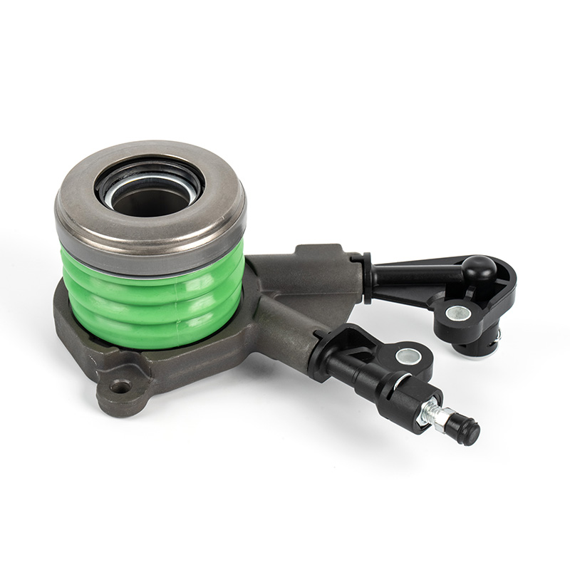
The CSC Throw Out Bearing Diagram — A Different Architecture
The concentric slave cylinder design deserves its own section because its diagram looks entirely different from the conventional fork-actuated layout. Many technicians trained on older vehicles misidentify CSC diagrams or attempt to adapt conventional bearing replacement procedures to CSC applications with expensive consequences.
What the CSC Diagram Shows
The CSC diagram is a cross-section through the hydraulic cylinder body. Key features visible in the drawing include:
- The hydraulic inlet port and bleed screw port on the outer housing
- The annular piston that slides axially within the cylinder bore
- The piston seal (usually EPDM lip seal or O-ring) and its axial position relative to the port
- The throw out bearing pressed or snap-fit onto the piston nose
- The return spring (if fitted) that keeps the bearing in contact with the pressure plate fingers
- The mounting flange bolt pattern that locates the CSC to the bell housing
There is no fork, no pivot stud, and no cable/rod in the diagram. The clutch master cylinder in the pedal box connects directly to this unit via a hydraulic line. The throw out bearing in this system sees a continuous preload force of 50 to 200 N (the contact force from the return spring or diaphragm spring pre-load) at all times, even when the pedal is released — which is why CSC throw out bearings must be rated for continuous operation, not intermittent use.
Common CSC Diagram Misreadings
The most frequent error when interpreting a CSC diagram is misidentifying the bleed port as a lubrication fitting. The two may look similar in a schematic but serve entirely different purposes. Attempting to grease a bleed port introduces lubricant into the hydraulic circuit, contaminating the brake/clutch fluid and destroying the piston seal within a few hundred kilometers.
The second common error is misreading the bearing's mounting method on the piston. Some CSC bearings are a press-fit and cannot be separated from the piston without destroying the piston; others use a snap ring and are serviceable separately. The diagram's section view makes this clear — a press-fit joint shows no groove or clip feature at the bearing-to-piston interface, while a snap-ring joint shows a groove and the clip cross-section.
On vehicles like the Volkswagen Group's DSG dual-clutch transmissions, there are actually two CSC units in the same bell housing — one for each partial transmission — and their diagrams are mirror images of each other. Confusing K1 and K2 bearings during reassembly results in a transmission that cannot disengage either clutch pack.
Performance and Racing Throw Out Bearing Diagram Differences
High-performance and racing throw out bearings are engineered to a different standard than OEM replacements, and their diagrams reflect these differences clearly. Understanding the diagram helps when specifying the correct performance bearing for a given power level.
Angular-Contact Bearing Design
Racing throw out bearings often replace the standard deep-groove ball bearing with an angular-contact design, visible in the diagram as a ball set positioned at an angle (typically 15° to 40°) relative to the race bore axis. This geometry allows the bearing to carry higher combined axial and radial loads without increasing envelope size. The Tilton Engineering 40-series clutch release bearing, for example, uses a matched set of angular-contact bearings rated to handle release loads up to 4,000 N — nearly three times the typical passenger car load.
Self-Aligning (Spherical) Contact Face
In the diagram of a self-aligning performance release bearing, the contact face shows a spherical or convex profile rather than a flat face. This geometry compensates for minor misalignment between the throw out bearing axis and the diaphragm spring finger plane — misalignment that becomes more significant in high-horsepower applications where engine torque reaction can shift the drivetrain under load. The spherical face redistributes contact stress, reducing the peak Hertzian contact stress that causes finger brinelling.
Adjustable Bearing Height
Some performance fork-actuated throw out bearings have an adjustable nose piece that changes the effective height of the contact face relative to the bearing body. In the diagram this is shown as a threaded collar with a lock nut. This allows the same bearing to be configured for different pressure plate finger heights — useful when mixing aftermarket pressure plates with existing fork geometry. Height adjustment range is typically ±5 mm.
Graphite Release Bearings (Vintage / Slipper Type)
Vintage racing diagrams sometimes show a graphite block release bearing — a slipper bearing that does not rotate but slides on the diaphragm spring fingers using a carbon-graphite face. There are no balls or races in this design. The diagram shows a solid graphite or carbon-filled PTFE pad in a steel carrier. This design requires continuous contact (zero free play) and generates friction heat that limits use to sustained-operation circuits rather than street driving with repeated engagement cycles.
Maintenance Intervals and When to Replace Based on Diagram Wear Indicators
Throw out bearings are classified as a wear item, and OEM guidance universally recommends replacing the bearing whenever the clutch disc and pressure plate are replaced — regardless of apparent bearing condition. The rationale is straightforward: the labor cost of removing the transmission again if the bearing fails shortly after a clutch service is many times the cost of the bearing itself.
50,000–80,000 km Mark
For heavy urban driving (frequent clutch use, stop-and-go), this is the first mileage at which throw out bearing inspection is advisable. If the transmission is being dropped for another reason (gearbox service, dual-mass flywheel replacement), the bearing should be examined for axial play greater than 0.3 mm and radial play greater than 0.2 mm, measured with the bearing on the input shaft sleeve.
Clutch Service Interval (Any Mileage)
Any clutch job is an automatic throw out bearing replacement. This is the industry standard recommendation from Sachs, LuK, Valeo, and Exedy — all of whom supply throw out bearings in their clutch kit packages precisely for this reason. Attempting to reuse an original bearing with a new clutch kit voids the clutch kit warranty on most brands.
Noise-Based Replacement (Any Mileage)
Clutch-pedal-dependent noise — noise that appears or disappears with pedal movement — is sufficient justification for throw out bearing replacement regardless of mileage. Ignoring this symptom risks complete bearing seizure, which can lock the clutch in a disengaged position (vehicle unable to engage drive) or cause contact face fragments to damage the pressure plate diaphragm fingers, turning a bearing replacement into a full clutch kit replacement.
CSC Hydraulic Leak (Any Mileage)
A CSC throw out bearing that begins to leak hydraulic fluid has a failed piston seal. Since the bearing is integral with the piston, the entire CSC unit must be replaced. Hydraulic fluid contamination of the clutch friction disc is the secondary consequence — even a small amount of clutch fluid on the disc surface reduces friction coefficient from approximately 0.35 to below 0.15, causing clutch slip at full torque.
Lubrication Points in the Throw Out Bearing Diagram
Every professional throw out bearing installation diagram marks specific lubrication points with a grease symbol. Applying lubricant to the wrong location — or using the wrong type — causes as many problems as applying none at all.
Input Shaft Retainer Sleeve / Hub Bore Interface
A light film of high-melting-point grease (NLGI grade 2, lithium complex or molybdenum disulfide base) is applied to the outside of the input shaft bearing retainer sleeve where the hub slides. The film must be thin — visible coverage with no excess. Excess grease migrates onto the clutch disc, contaminating the friction surface.
Fork Pivot Ball Stud
The fork pivot socket receives a small amount of the same high-melting-point grease. On ball-stud pivots, grease is applied to the ball surface. On shaft-type pivots, the bushings at each end of the fork shaft receive grease through a Zerk fitting if present, or at disassembly.
Fork Tips at Hub Contact Points
Where the fork tips contact the bearing hub ears or groove, a small amount of grease prevents fretting corrosion and reduces the stick-slip that causes clutch pedal chatter. Only the contact area — not the entire fork tip — receives grease.
Do NOT Lubricate: Bearing Contact Face
The throw out bearing contact face that touches the diaphragm spring fingers must remain dry. Grease on this surface creates a slip plane that can cause the fingers to walk across the bearing face eccentrically, producing vibration and accelerating wear on both components. Modern bearings are factory-greased internally and sealed — they require no additional lubrication.
Frequently Asked Questions About Throw Out Bearing Diagrams and Replacement
What is the difference between a throw out bearing and a release bearing?
They are the same component referred to by two different names. "Throw out bearing" is the traditional North American term. "Release bearing" is more common in European service literature and in OEM parts catalogs from manufacturers like ZF, Sachs, and Valeo. Some service diagrams use "clutch release bearing" (CRB) as the formal designation. All three terms describe the same bearing that disengages the clutch when the pedal is pressed.
Can I diagnose a bad throw out bearing without removing the transmission?
Yes, with reasonable confidence. A failing throw out bearing almost always produces noise that is specifically tied to clutch pedal position. With the engine running, slowly depress the clutch pedal. If a noise (squeal, grind, or chirp) begins as soon as the pedal starts to move and then changes character or stops near the floor, the throw out bearing is the primary suspect. If the noise is present at all times regardless of pedal position, the issue is more likely in the transmission itself. This pedal-dependent noise test correlates directly to the diagram's resting-vs.-released bearing position: only the bearing moves when the pedal moves, so noise that tracks with pedal travel must come from the bearing or its immediate contact points.
How does the throw out bearing diagram differ for a pull-type clutch vs. a push-type clutch?
In a push-type clutch (the most common design), the throw out bearing is on the gearbox side of the pressure plate and is pushed toward the engine to depress the diaphragm spring fingers. In a pull-type clutch, the release mechanism is on the engine side of the pressure plate, and the bearing pulls the fingers away from the flywheel side. The diagram's force arrow and bearing travel direction reverse completely between the two designs. Pull-type clutches were historically common on agricultural equipment and some European trucks (Eaton Fuller, for example) but appear occasionally on high-performance aftermarket setups because they offer a more consistent pedal feel at high clamping loads.
What does it mean when the throw out bearing diagram shows a "self-centering" feature?
Self-centering (also called floating or self-aligning) throw out bearings have a hub-to-outer-body fit that permits a small amount of radial float — typically 0.5 to 2.0 mm of radial movement — between the hub that rides on the input shaft sleeve and the outer body that contacts the pressure plate. This float allows the bearing to align itself with the pressure plate's diaphragm spring finger tips even if the clutch is not perfectly concentric with the input shaft. The diagram shows this as a clearance gap between the hub OD and the outer carrier ID, often with a wave spring or centering spring that keeps the outer body centered during non-engagement without preventing radial movement under load.
Why does my new throw out bearing make noise immediately after installation?
New throw out bearing noise immediately after installation almost always indicates one of three installation errors visible in the diagram: (1) The free play was not set correctly and the bearing is contacting the pressure plate fingers at rest, running under continuous load and generating heat noise. (2) The hub sleeve was not lubricated before installation, so the bearing is binding on the input shaft retainer and not sliding freely. (3) The fork tips are not seated correctly in the hub groove, causing the bearing to tilt off-axis and contact the pressure plate fingers at an angle. Return to the diagram's clearance dimension and fork engagement depth dimension to verify these three points before assuming the bearing itself is defective.
Is there a way to replace only the throw out bearing without replacing the whole clutch kit?
Technically yes, but it is not recommended practice. Replacing only the throw out bearing still requires full transmission removal on most vehicles — equivalent labor to a complete clutch job. Since the clutch disc, pressure plate, and throw out bearing wear at related rates (they are all subject to the same engagement cycle count), installing a new bearing against a worn pressure plate and disc means the new bearing will encounter worn diaphragm spring fingers that may be uneven in height (beyond the 0.5 mm tolerance shown in the diagram's spec block), causing the same vibration and accelerated wear patterns from day one. The cost of the bearing kit versus a complete clutch kit is typically less than 15–25% of the total repair cost, making part substitution economically irrational.
Do electric vehicles (EVs) have throw out bearings?
Standard battery-electric vehicles (BEVs) do not have manual clutches and therefore have no throw out bearing. The electric motor connects to the drive wheels through a fixed-ratio single-speed reduction gear with no clutch mechanism. However, some performance EV applications and certain hybrid configurations use automated manual transmissions or dual-clutch transmissions that retain clutch packs — in these cases, electrically actuated CSC units are used and they do contain a throw out bearing, though it is controlled by an electronic clutch actuator rather than a pedal-operated hydraulic circuit.
What grease goes on the input shaft sleeve when installing a throw out bearing?
The throw out bearing diagram's lubrication note specifies a high-temperature, high-melting-point grease compatible with the clutch environment. Most OEM and clutch kit manufacturers (LuK, Sachs, Valeo, Exedy) include a small sachet of appropriate grease in the clutch kit. If sourcing separately, a molybdenum disulfide (MoS2) grease, NLGI grade 2, with a dropping point above 180°C is appropriate. Copper anti-seize compound is sometimes used by technicians but is not ideal because it can migrate more easily and its high thermal conductivity can accelerate heat transfer into the bearing hub. Never use wheel bearing grease or chassis grease — both are too soft and will liquefy under clutch heat, migrating onto the disc surface.
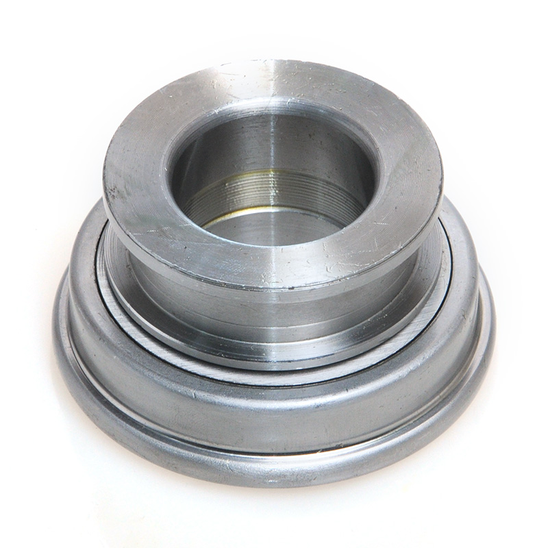
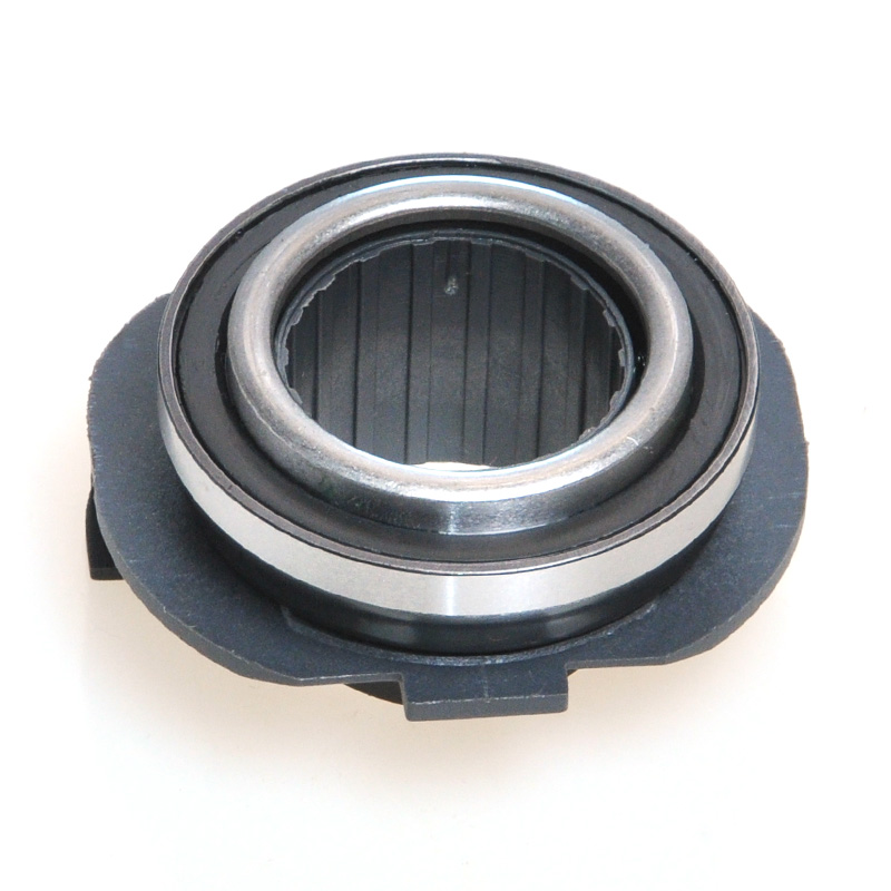
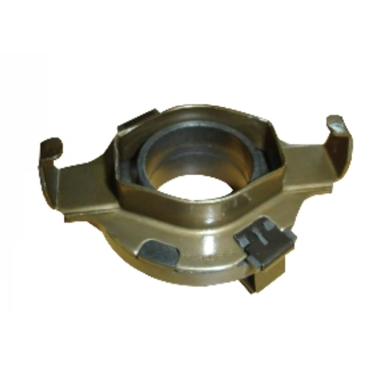
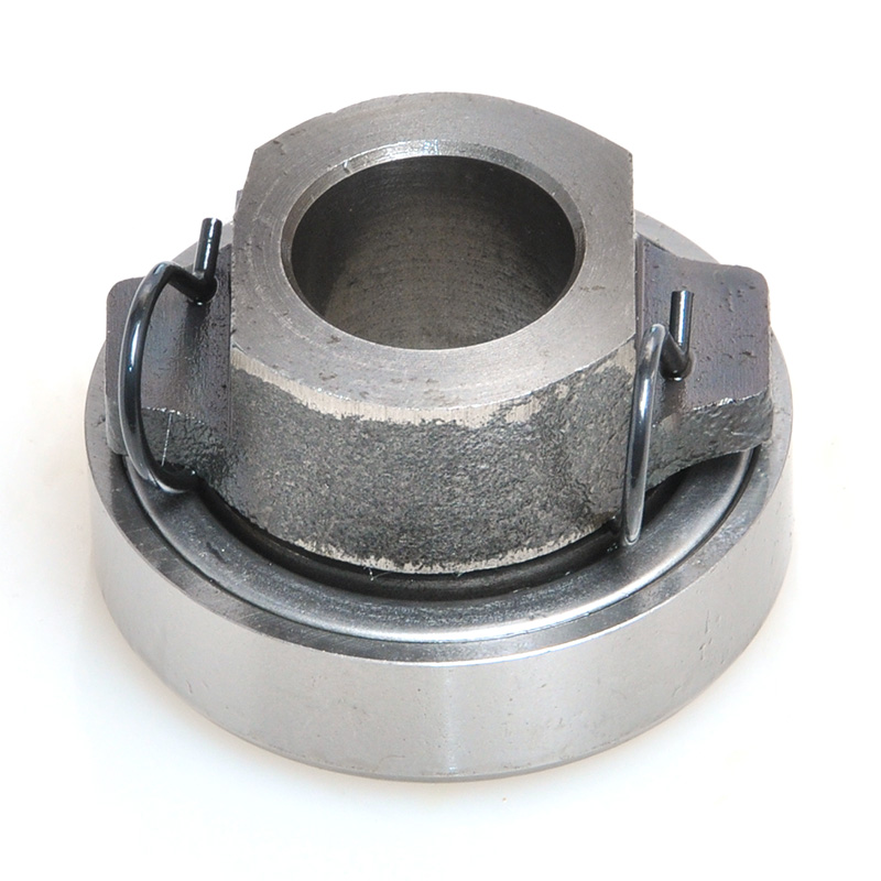
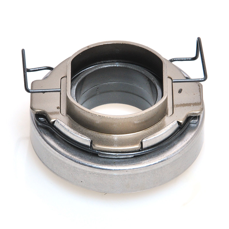
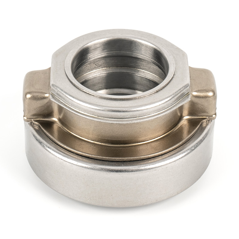
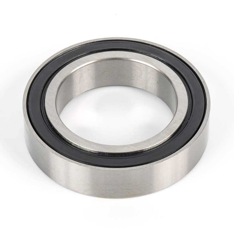
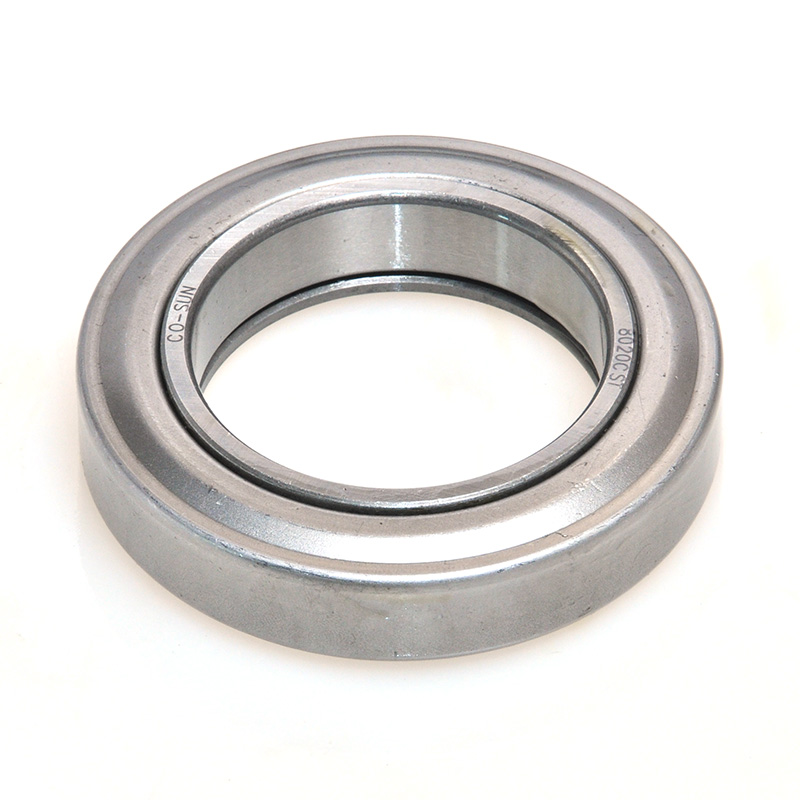
Related products
Contact Us
A production enterprise specializing in the production of automobile clutch bearings and other non-standard bearings.
- Contact Information
-
 +86-575-86013311
 -
 +86-575-86013322
 -
 No. 50, Tashan 1st Road, Xinchang County, Shaoxing, Zhejiang, China
Copyrigh t© Xinchang Heyang Auto Parts Co., Ltd.. All Rights Reserved.
China auto bearing manufacturers wholesale auto bearing supplier
