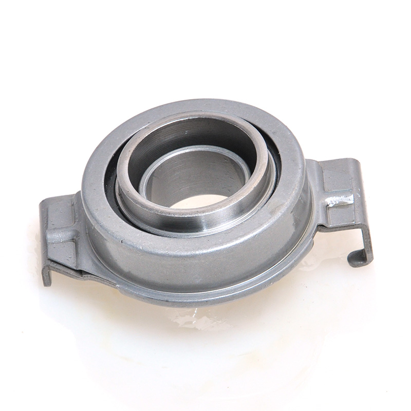
What a Ball Bearing Specification Chart Actually Tells You
A ball bearing specification chart is a structured reference that maps every critical dimensional and performance parameter of a rolling-element bearing onto a single, readable format. At a glance it reveals bore diameter, outer diameter, width, dynamic load rating, static load rating, limiting speed, and basic designation — everything an engineer needs to select, replace, or cross-reference a bearing without pulling apart an assembly. The most important column in any bearing specification chart is the dynamic load rating (C), expressed in kilonewtons, because it directly determines the L10 fatigue life of the bearing under a given radial or axial load. If you understand only one number on the chart, make it that one.
This article walks through every column of a standard ball bearing specification chart, explains what the numbers mean in practice, covers the main bearing series families (600, 6000, 6200, 6300, 7000), and gives real-world selection examples so you can move from chart to purchase order with confidence.
Anatomy of a Standard Ball Bearing Specification Chart
Every reputable bearing manufacturer — SKF, NSK, FAG, NTN, Timken — publishes specification charts that follow ISO 15 and ISO 281 conventions, so the column headers are largely interchangeable once you know what each abbreviation means.
Core Dimensional Columns
The first three columns of any ball bearing specification chart are always the same: d (bore diameter in mm), D (outer diameter in mm), and B (width in mm). These three values, taken together, define the bearing envelope and determine whether the bearing will physically fit the shaft and housing. For a 6205 deep groove ball bearing, for example, d = 25 mm, D = 52 mm, and B = 15 mm. Those numbers will be identical regardless of which ISO-compliant manufacturer you consult.
Many charts also include the fillet radius r (the transition radius at the ring corners), which matters when designing shaft shoulders and housing bores — if the corner radius of the shaft exceeds r, the bearing will not seat flush and fretting corrosion will result.
Load Rating Columns
After dimensions, the two most consequential columns are C (basic dynamic load rating, kN) and C₀ (basic static load rating, kN).
- C is the radial load that a group of identical bearings can theoretically endure for one million revolutions with 90% of the group surviving. For a 6205, C is typically 14.0 kN.
- C₀ is the maximum load the bearing can sustain when stationary or oscillating without permanent deformation of the raceways. For the same 6205, C₀ is typically 6.55 kN.
- The ratio C/C₀ reflects the bearing's sensitivity to shock loads. A higher ratio indicates the bearing tolerates dynamic overloads better relative to its static capacity.
Speed Columns
Most charts list two speed values: the grease limiting speed and the oil limiting speed, both in rpm. For a 6205, grease limiting speed is around 15,000 rpm and oil limiting speed around 18,000 rpm. Operating a bearing above its limiting speed without adequate lubrication engineering will cause thermal runaway within minutes. Speed limits depend on dm·n (pitch diameter in mm multiplied by rpm), not just rpm alone, which is why larger-diameter bearings have lower speed ratings even with identical internal geometry.
Mass Column
Often overlooked, the mass column (grams or kilograms) matters in aerospace, robotics, and high-speed spindle applications where the rotational inertia of the bearing itself contributes to system dynamics. A 6001 bearing weighs roughly 18 g; a 6312 bearing in the same series family weighs about 710 g — nearly 40 times as much.
Ball Bearing Specification Chart — 6200 Series (Deep Groove)
The 6200 series is the most widely stocked deep groove ball bearing family in the world. The table below covers bore sizes from 10 mm to 80 mm and lists all major specification columns you will find in OEM catalogs.
| Designation |
d (mm) |
D (mm) |
B (mm) |
C (kN) |
C₀ (kN) |
Grease Speed (rpm) |
Mass (g) |
| 6200 |
10 |
30 |
9 |
5.10 |
2.36 |
26,000 |
25 |
| 6201 |
12 |
32 |
10 |
6.82 |
3.05 |
22,000 |
33 |
| 6202 |
15 |
35 |
11 |
7.65 |
3.72 |
19,000 |
45 |
| 6203 |
17 |
40 |
12 |
9.56 |
4.75 |
17,000 |
60 |
| 6204 |
20 |
47 |
14 |
12.7 |
6.55 |
15,000 |
96 |
| 6205 |
25 |
52 |
15 |
14.0 |
7.88 |
13,000 |
130 |
| 6206 |
30 |
62 |
16 |
19.5 |
11.2 |
11,000 |
210 |
| 6207 |
35 |
72 |
17 |
25.7 |
15.3 |
9,500 |
310 |
| 6208 |
40 |
80 |
18 |
29.5 |
18.0 |
8,500 |
420 |
| 6210 |
50 |
90 |
20 |
35.1 |
23.2 |
7,500 |
590 |
| 6212 |
60 |
110 |
22 |
47.5 |
32.5 |
6,300 |
970 |
| 6216 |
80 |
140 |
26 |
72.0 |
51.2 |
4,800 |
2,020 |
Table 1. 6200 Series deep groove ball bearing specification chart — ISO standard values. Dynamic load ratings per ISO 281.
How to Read a Ball Bearing Designation Number
The designation printed on a bearing's outer ring is a compact specification chart in its own right. Once you know the coding scheme you can extract the bore, series, and special features without looking up a single number.
The Basic Format: Series Code + Bore Code
For deep groove ball bearings the designation reads: 6 [series digit] [two-digit bore code]. The leading "6" identifies the bearing as a deep groove ball bearing type. The series digit immediately following controls the cross-section (width and outer diameter relative to bore): 0 = extra light, 1 = extra light, 2 = light, 3 = medium, 4 = heavy. The last two digits encode the bore diameter.
Bore encoding works as follows:
- 00 = 10 mm bore
- 01 = 12 mm bore
- 02 = 15 mm bore
- 03 = 17 mm bore
- 04 and above: multiply the two-digit code by 5 to get bore in mm (e.g., 05 = 25 mm, 12 = 60 mm)
Suffix Codes That Change the Specification
Suffix codes appended after the number alter the bearing significantly and should be checked against the specification chart before ordering:
- 2RS / 2RSH — Rubber contact seals on both sides. Reduces speed limit typically by 30–40% but enables grease-for-life packing.
- ZZ / 2Z — Metal shields on both sides. Lower drag than 2RS; suitable for higher speeds.
- C3 — Radial internal clearance group 3, larger than normal. Required when bearing will run hot (above 100°C) or when interference fits reduce clearance.
- NR — Snap ring groove in outer ring. Simplifies axial positioning in housings.
- N — Single groove in outer ring for snap ring.
- P5 / P6 — ABEC 5 or ABEC 6 precision tolerance. Standard bearings are ABEC 1 or P0.
A designation like 6205-2RS1/C3 therefore tells you: deep groove ball bearing, 200 series (light cross-section), 25 mm bore, rubber-sealed both sides, clearance group 3. Every one of those facts maps to a distinct column or sub-table in the manufacturer's specification chart.
Comparing Ball Bearing Series: 600, 6000, 6200, 6300, 7200
Choosing the right series is as important as selecting the right bore size. The series governs how much load capacity you get in a given shaft diameter, and the trade-off is always envelope size versus rated life. The table below compares the most common series for a 25 mm bore shaft to make the trade-off concrete.
| Designation |
Series |
D (mm) |
B (mm) |
C (kN) |
C₀ (kN) |
Grease Speed (rpm) |
Best Use Case |
| 625 |
600 (miniature) |
16 |
5 |
1.17 |
0.56 |
40,000 |
Instruments, RC motors |
| 6005 |
6000 (extra light) |
47 |
12 |
11.2 |
5.85 |
14,000 |
Small motors, pumps |
| 6205 |
6200 (light) |
52 |
15 |
14.0 |
7.88 |
13,000 |
General machinery |
| 6305 |
6300 (medium) |
62 |
17 |
22.5 |
11.4 |
11,000 |
Gearboxes, conveyors |
| 7205 |
7200 (angular contact) |
52 |
15 |
14.3 |
10.2 |
15,000 |
Spindles, combined loads |
Table 2. Series comparison for 25 mm bore ball bearings. Angular contact bearing (7205) rated for combined radial + axial loading.
The data shows clearly that stepping up from the 6200 to the 6300 series adds 10 mm to the outer diameter but increases the dynamic load rating by 60% (14.0 kN to 22.5 kN). That is a significant life gain when L10 life is calculated: at a 5 kN radial load, the 6305 delivers roughly 3.8 times the fatigue life of the 6205 despite only modest dimensional growth.
Using the Specification Chart to Calculate Bearing L10 Life
The dynamic load rating C in the specification chart feeds directly into the ISO 281 life formula. Understanding this calculation lets you verify whether the bearing you selected will survive its design interval — or whether you need to step up a series.
The Basic L10 Life Formula
L10 = (C / P)^3 × 10^6 revolutions, where C is from the specification chart in Newtons and P is the equivalent dynamic bearing load in Newtons. For a ball bearing, the exponent is 3; for a roller bearing it is 10/3.
To convert to hours: L10h = L10 / (60 × n), where n is the rotational speed in rpm.
Worked Example
A 6205 bearing (C = 14,000 N from the specification chart) carries a 3,500 N purely radial load at 1,450 rpm (a 4-pole induction motor speed). No axial load, so P = Fr = 3,500 N.
- L10 = (14,000 / 3,500)^3 × 10^6 = 4^3 × 10^6 = 64,000,000 revolutions
- L10h = 64,000,000 / (60 × 1,450) = 64,000,000 / 87,000 ≈ 735 hours
That is only 735 hours — about 30 days of continuous operation — which is far too short for most industrial motors. Replacing it with a 6305 (C = 22,500 N):
- L10 = (22,500 / 3,500)^3 × 10^6 = 6.43^3 × 10^6 ≈ 266,000,000 revolutions
- L10h ≈ 266,000,000 / 87,000 ≈ 3,057 hours
The specification chart made that difference visible in under two minutes of arithmetic. This is exactly why the C column is the most important number to consult before finalizing a bearing selection.
The Life Modification Factor a1
Modern ISO 281 includes a life modification factor a1 that adjusts L10 for reliability. For 90% survival (standard L10) a1 = 1. For 95% survival, a1 = 0.62. For 99% survival, a1 = 0.21. If your application demands 99% bearing survival — medical devices, aircraft ground support equipment, continuous process lines — multiply your basic L10 by 0.21. That means a bearing calculated for 3,000 hours at 90% reliability survives only 630 hours at 99% reliability under the same load. The specification chart gives you C; you must apply the correct a1 factor for your reliability target.
Internal Clearance Groups in the Specification Chart
Internal radial clearance — the total radial movement of the inner ring relative to the outer ring when no load is applied — is a specification parameter often buried in a sub-table or footnote of the main bearing chart. It is one of the most frequently misunderstood numbers in bearing selection.
| Clearance Group |
ISO Designation |
Typical Radial Clearance (6205, μm) |
When to Use |
| C2 |
Below normal |
3–18 |
Precision spindles, low noise |
| CN (standard) |
Normal |
11–25 |
General applications, clearance fit shaft |
| C3 |
Greater than normal |
18–36 |
Interference fit, elevated temperature, electric motors |
| C4 |
Greater than C3 |
25–51 |
High-temperature ovens, furnace fans |
| C5 |
Greater than C4 |
36–66 |
Extreme temperature differentials |
Table 3. Radial internal clearance groups for 6205 deep groove ball bearing. Values per ISO 5753-1.
The most common installation mistake in bearing selection is using a standard-clearance (CN) bearing on an interference-fit shaft without upgrading to C3. A tight interference fit reduces internal clearance by 10–20 μm in a 25 mm bore bearing. A CN bearing with 11–25 μm clearance can end up with negative clearance (preload) after pressing onto the shaft, dramatically shortening life. Electric motor manufacturers almost universally specify C3 as their default clearance group for this reason.
Precision Tolerance Classes and What They Mean for Specification
Dimensional tolerances for ball bearings are standardized under ISO 492 (radial) and ABEC in North America. The standard class equivalences are:
- ISO P0 / ABEC 1 — Standard tolerance. The default for most industrial bearings in a specification chart. Bore tolerance for a 25 mm bearing: −0 to +12 μm.
- ISO P6 / ABEC 3 — Tighter bore and runout tolerances. Bore tolerance: −0 to +8 μm. Used for better running accuracy in machine tools.
- ISO P5 / ABEC 5 — Precision class. Bore tolerance: −0 to +5 μm. Required for CNC spindle bearings, precision gearboxes.
- ISO P4 / ABEC 7 — High precision. Bore tolerance: −0 to +4 μm. Used in precision instrument bearings, high-speed grinding spindles.
- ISO P2 / ABEC 9 — Ultra-precision. Bore tolerance: −0 to +2.5 μm. Gyroscopes, precision inertial sensors.
Precision class bearings carry a significant price premium: an ABEC 5 (P5) bearing typically costs 3–5 times the price of the equivalent ABEC 1 (P0) part. A specification chart for precision bearings will include additional columns for radial runout (Kr), axial runout (Ka), and ring taper that do not appear in standard catalog charts.
Angular Contact Ball Bearing Specification Chart — 7200 Series
Angular contact bearings carry both radial and axial (thrust) loads simultaneously, which deep groove bearings do poorly. The key additional column in an angular contact bearing specification chart is the contact angle, expressed in degrees.
| Designation |
Contact Angle |
d (mm) |
D (mm) |
C radial (kN) |
C axial (kN) |
Grease Speed (rpm) |
| 7205B |
40° |
25 |
52 |
13.0 |
10.4 |
15,000 |
| 7205C |
15° |
25 |
52 |
14.3 |
6.2 |
17,000 |
| 7206B |
40° |
30 |
62 |
20.0 |
16.0 |
13,000 |
| 7208B |
40° |
40 |
80 |
31.5 |
25.0 |
9,500 |
Table 4. 7200 series angular contact ball bearing specification chart. Suffix B = 40° contact angle; C = 15° contact angle.
Contact angle directly affects the axial-to-radial load ratio the bearing can handle. A 40° angle (suffix B) carries 80% more axial load than a 15° angle bearing of the same bore, but the trade-off is slightly lower radial capacity and reduced speed limit. Machine tool spindles running at high speed typically use 15° or 25° contact angle bearings paired back-to-back (DB or DF arrangement), while screw drives and ball screw supports benefit from the 40° angle.
Material and Lubrication Data in Extended Specification Charts
Standard catalog charts cover dimensions and load ratings. Extended specification charts — typically found in OEM engineering datasheets — add material grades, lubrication data, and temperature ranges that are critical for harsh environments.
Ring and Ball Material Options
Standard deep groove ball bearings use through-hardened chromium steel (100Cr6 / AISI 52100). This is assumed in all standard specification chart load ratings. Substitute materials alter the ratings:
- Stainless steel (AISI 440C) — Used in food processing, pharmaceutical, and marine environments. Dynamic load rating is typically 20–30% lower than the equivalent 52100 bearing due to lower hardness.
- Silicon nitride (Si3N4) balls — Hybrid bearings with ceramic balls and steel rings. Reduces ball density by 60% (3.2 g/cm³ vs 7.8 g/cm³ for steel), lowers centrifugal load at high speeds, and increases limiting speed by up to 40%.
- Full ceramic (Zirconia or Si3N4) — Non-conductive, corrosion-resistant, suitable for high-frequency electrical applications and strong acid environments. Dynamic load ratings are 40–60% of equivalent steel bearings.
Grease Specification Columns
Pre-greased sealed or shielded bearings include grease type and fill volume in the extended specification chart. Typical entries look like: "Grease: Li-soap based, NLGI 2, fill 30% of free space, temperature range −30°C to +120°C." Replacing a sealed bearing with a different manufacturer's equivalent should include verifying the grease compatibility — some synthetic greases are incompatible with certain seal materials and cause rapid seal degradation.
Grease fill percentage is a critical specification: too little grease causes starvation, too much causes churning and heat buildup. At high speeds (above ndm = 300,000 mm·rpm), over-greasing is more destructive than under-greasing because viscous drag generates temperatures that rapidly degrade the lubricant and seals.
Cross-Referencing Bearing Specifications Across Manufacturers
ISO standardization means that any 6205 bearing from NSK, SKF, FAG, NTN, or Koyo will have the same bore (25 mm), OD (52 mm), and width (15 mm). The load ratings and speed limits should be nearly identical because they are all derived from the same geometry. However, there are genuine differences to watch for when cross-referencing a specification chart.
Where Manufacturers Actually Differ
- Steel purity and heat treatment — Premium brands publish fatigue life factors (aISO) based on lubricant viscosity ratio and contamination level. Bearings made from vacuum-degassed steel (VIM-VAR for aerospace grades) can achieve 3–5 times the L10 life calculated from the standard C value.
- Cage design — Steel pressed cage (standard), polyamide 66 cage (for speeds above 70% of limiting speed), machined brass cage (for very high speeds or high temperatures). The specification chart will identify cage material with a suffix such as "TN9" for polyamide or "M" for brass.
- Internal geometry — Ball complement (number of balls) and osculation (ball-to-raceway conformity ratio) vary between manufacturers and directly affect load distribution. A bearing with 8 balls has different fatigue characteristics than one with 9 balls of the same diameter, even though both meet the published C value.
- Noise grades — SKF uses E2 (low friction) and Explorer designations; NSK uses PS2 (quiet); FAG uses X-life. These are not interchangeable product lines and their published load ratings may be higher than the equivalent standard product despite the same designation number.
Practical Cross-Reference Steps
- Identify the full designation on the failed or existing bearing, including all suffixes.
- Look up d, D, B, C, and C₀ from the original manufacturer's specification chart.
- Find a candidate from the substitute manufacturer whose specification chart matches on all five values within ±5%.
- Verify seal/shield type, clearance group, and cage material match the original suffix codes.
- Check fillet radius r — if the shaft shoulder was designed for the original bearing's r, a substitute with a larger r may not seat correctly.
Bearing Specification Chart Selection Guide by Application Type
Rather than working through the full specification chart every time, experienced engineers develop application-specific starting points. The following guidance maps common machinery to the correct bearing series and key specification values to prioritize.
Electric Motors (IEC Frame Sizes)
Most IEC frame motors use 6200 or 6300 series deep groove ball bearings in C3 clearance. Drive-end (DE) bearing carries radial belt or coupling load plus axial float; specify C based on actual resultant load, not just rated motor torque. Non-drive-end (NDE) bearing is lightly loaded; in many designs it is one series step smaller than the DE bearing. Speed: check that motor synchronous speed (50 Hz: 3,000/1,500/1,000 rpm; 60 Hz: 3,600/1,800/1,200 rpm) is below the grease limiting speed in the specification chart. C3 clearance is mandatory for motors over 7.5 kW frame size with direct-on-line starting.
Conveyor Idler Rollers
Conveyor idlers rotate continuously at low speed (50–300 rpm) under steady radial load. Life requirement is often 30,000–50,000 hours. Required C = P × (L10h × 60 × n / 10^6)^(1/3). For a 10 kN idler load at 150 rpm targeting 40,000 hours: C = 10,000 × (40,000 × 60 × 150 / 10^6)^(1/3) = 10,000 × (360)^(1/3) ≈ 10,000 × 7.11 = 71.1 kN. That points to a 6316 or 6318 bearing in the specification chart.
CNC Machine Tool Spindles
High-speed spindles demand P5 or P4 precision, angular contact bearing type (7000 series), 15° or 25° contact angle for high-speed capability, and ceramic hybrid balls for maximum ndm values. Operating speeds up to 20,000 rpm are common for milling spindles. The specification chart column to check first is limiting speed (oil lubrication), as oil-air mist lubrication can push the practical limit to 80–90% of the oil limit. Load ratings are less critical than precision and speed capacity for spindle applications.
Agricultural and Off-Road Equipment
Heavy shock loads, contamination, and misalignment characterize this segment. Deep groove ball bearings in a C4 clearance or spherical roller bearings are typical. When ball bearings are used, the C₀ (static load rating) column becomes as important as C, because impact loads during field operation can briefly exceed the dynamic load capacity. A static safety factor C₀/P₀ of 3–5 is standard practice for agricultural applications.
Miniature Ball Bearing Specification Chart — 600 and MR Series
Miniature and instrument ball bearings (bore diameters 1 mm to 9 mm) follow slightly different specification conventions. The 600 series covers 1–9 mm bores with standard metric ODs; the MR series uses metric bore with non-standard ODs for tighter packaging. Both series are widely used in RC cars, drones, medical instruments, and precision optics.
| Designation |
d (mm) |
D (mm) |
B (mm) |
C (N) |
C₀ (N) |
Limiting Speed (rpm) |
| 601 |
1 |
6 |
3 |
91 |
31 |
90,000 |
| 603 |
3 |
9 |
4 |
310 |
110 |
60,000 |
| 604 |
4 |
12 |
4 |
520 |
195 |
50,000 |
| 606 |
6 |
17 |
6 |
1,270 |
485 |
36,000 |
| MR84 |
4 |
8 |
3 |
355 |
128 |
55,000 |
| MR104 |
4 |
10 |
4 |
475 |
180 |
52,000 |
Table 5. Miniature ball bearing specification chart — 600 and MR series. Load ratings in Newtons for miniature bearings.
Note that miniature bearing specification charts express C in Newtons, not kilonewtons. A 601 bearing (1 mm bore) has C = 91 N — roughly 0.09 kN — because the tiny balls and thin raceways have very limited contact area. Miniature bearings compensate with high speed capability: a 601 bearing has a 90,000 rpm limiting speed compared to 13,000 rpm for a 6205. The product ndm (speed × pitch diameter) stays within the thermal limits despite the extreme shaft speed.
Common Mistakes When Reading a Ball Bearing Specification Chart
Misreading specification charts is one of the leading causes of premature bearing failure in maintenance and design settings. The following are the most frequent errors, with concrete numbers to illustrate each one.
Confusing C and C₀
C (dynamic) and C₀ (static) appear in adjacent columns and are superficially similar numbers. Using C₀ when you meant C in an L10 life calculation understates your bearing capacity — for a 6208 bearing C = 29,500 N while C₀ = 18,000 N, a 39% difference. In low-speed, oscillating, or shock-load applications, C₀ is the correct column to reference for the safety factor calculation, not C.
Ignoring Speed Reduction for Sealed Bearings
Sealed (2RS) bearings have a grease limiting speed 30–40% lower than the open or shielded equivalent. An open 6205 has a limiting speed of 13,000 rpm. The 6205-2RS variant is typically rated to around 8,500 rpm. Using a sealed bearing in an application that calls for the open bearing's speed rating is a frequent maintenance error that causes premature seal wear and thermal grease degradation.
Applying Radial Ratings to Purely Axial Loads
The C column in a deep groove bearing specification chart is the radial dynamic load rating. For purely thrust (axial) loads, you must convert to an equivalent radial load using the X and Y factors tabulated in the bearing catalog. For a 6205 with Fa/C₀ = 0.025, the Y factor is approximately 1.96, meaning a 500 N axial load is equivalent to 500 × 1.96 = 980 N radial load for life calculation purposes.
Neglecting the Requisite Clearance After Interference Fit
As discussed in the clearance section, a bearing pressed onto a shaft shrinks in internal clearance by approximately 70–80% of the diametral interference. For a 25 mm bore bearing with 15 μm interference fit, clearance reduction is 11–12 μm. A CN-clearance bearing starting with 11 μm minimum clearance could end up at zero clearance — creating preload and greatly reducing life. The specification chart tells you the initial clearance range; it is the engineer's job to account for the interference fit reduction.
Verifying Bearing Specifications Against Counterfeits
The global counterfeit bearing market is estimated to represent 10–15% of total bearing trade volume. Counterfeit bearings typically carry the same designation as genuine product but may have load ratings 40–60% lower than stated, incorrect internal geometry, inferior steel hardness, and incompatible grease. The specification chart is your primary tool for catching substitution.
When receiving bearings, check the following against the specification chart values:
- Dimensional verification — Measure d, D, and B with a calibrated micrometer and compare to specification chart values. Genuine ISO bearings should be within tolerance (P0: bore +0/−12 μm for 25 mm). Counterfeit bearings often have dimensional scatter of ±50–100 μm.
- Mass check — Weigh the bearing and compare to the mass column in the specification chart. A genuine 6205 should weigh 130 ±5 g. A bearing that is more than 10% light likely has thinner rings or fewer balls than the genuine product.
- Cage inspection — Count the number of balls. A genuine 6205 has 9 balls. A counterpart with 8 balls will have approximately 20% lower load capacity, but the designation on the ring will still say 6205.
- Hardness spot check — Genuine 52100 bearing rings are hardened to 58–65 HRC. A Rockwell test on the ring OD of a suspect batch is a fast check that requires only basic lab equipment.
 +86-13867573512