 +86-13867573512
 [email protected]
What Is the Number One Cause of Bearing Failure?
Author: Heyang Date: Apr 06, 2026
Content
- 1 The Number One Cause of Bearing Failure Is Lubrication-Related
- 2 Why Lubrication Failure Dominates Bearing Damage Statistics
- 3 The Full Breakdown: Major Causes of Bearing Failure by Percentage
- 4 Contamination: The Second Most Destructive Force Acting on Bearings
- 5 Improper Installation: A Cause of Bearing Failure That Is Entirely Preventable
- 6 Rolling Contact Fatigue: The Natural End of Bearing Life
- 7 Electrical Erosion in Bearings: A Growing Problem in Modern Equipment
- 8 How to Identify a Bearing Failure Cause After the Fact
- 9 Practical Steps to Prevent Premature Bearing Failure
- 10 Bearing Selection Errors That Shorten Service Life Before the Bearing Is Even Installed
- 11 The Real Cost of Bearing Failure in Industrial Operations
- 12 Summary: Addressing Bearing Failure Starts with Lubrication, Then Everything Else
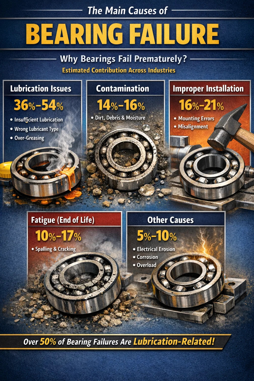
The Number One Cause of Bearing Failure Is Lubrication-Related
If you want a direct answer: inadequate or improper lubrication is the leading cause of bearing failure, responsible for an estimated 36% to 54% of all premature bearing failures, depending on the industry and application. Some studies conducted by major bearing manufacturers — including SKF and NSK — place the figure even higher when you factor in contamination cases that are themselves rooted in lubrication management failures.
Bearings are precision-engineered components. The rolling elements, raceways, and cages operate under enormous stress, often at high speeds and temperatures. Without the correct lubricant film separating metal surfaces, direct contact occurs, leading to rapid wear, heat generation, surface fatigue, and ultimately catastrophic failure. The physics are straightforward: metal on metal at speed generates heat, heat degrades the material, and degraded material fails.
That said, bearing failure is rarely caused by a single isolated factor. Lubrication problems often trigger or accelerate other failure modes. Understanding the full spectrum of causes — and how they interact — is essential for anyone managing rotating equipment, whether in a manufacturing plant, a wind turbine, an automotive drivetrain, or a food processing line.
Why Lubrication Failure Dominates Bearing Damage Statistics
Lubrication failure is not simply a matter of running out of grease or oil. It encompasses a wide range of conditions that prevent the lubricant from doing its job. Each of these conditions produces distinct damage patterns on the bearing surfaces.
Insufficient Lubrication Volume
When a bearing does not receive enough lubricant, the elastohydrodynamic film that separates rolling elements from raceways becomes too thin to prevent metal-to-metal contact. This results in adhesive wear, smearing, and localized heat spikes. In electric motors running at 1,500 RPM or above, metal surfaces can reach destructive temperatures within minutes of lubricant starvation.
Wrong Lubricant Type or Viscosity
Using a lubricant with the wrong viscosity grade for the application speed and temperature is one of the most common maintenance errors. A lubricant that is too thin cannot maintain an adequate film under load; one that is too thick generates excessive heat through churning and drag. For high-speed spindle bearings, for example, using a standard NLGI 2 grease instead of a low-viscosity oil or NLGI 1 grease dramatically increases operating temperature and shortens bearing life.
Over-Greasing
Counterintuitively, too much lubricant is also a significant problem. Over-greased bearings experience elevated internal temperatures due to churning, which breaks down the grease base oil and thickener, leading to leakage and hardening. Over-greasing accounts for a substantial share of bearing failures in electric motors, where technicians often apply grease without purging old material, compounding the problem over time.
Lubricant Degradation
Grease and oil have finite service lives. Heat cycling, oxidation, water ingress, and mechanical shearing all degrade lubricant performance over time. A grease that tested perfectly at commissioning may have lost most of its protective capacity after 4,000 to 8,000 hours of service, depending on operating conditions. Many maintenance intervals are set based on calendar time rather than actual condition, leading to bearings running on spent lubricant long past its effective life.
The Full Breakdown: Major Causes of Bearing Failure by Percentage
Different sources categorize bearing failure causes in slightly different ways, but the major contributing factors are consistent across industry studies. The table below reflects data compiled from research published by bearing manufacturers and reliability engineering organizations.
| Failure Cause | Estimated Contribution | Primary Damage Mode |
|---|---|---|
| Lubrication-related (all types) | 36% – 54% | Wear, smearing, overheating |
| Contamination | 14% – 16% | Abrasion, pitting, false brinelling |
| Improper mounting / installation | 16% – 21% | Overload, misalignment fractures |
| Fatigue (normal end-of-life) | 10% – 17% | Spalling, subsurface cracking |
| Other / miscellaneous | 5% – 10% | Electrical erosion, corrosion, overload |
These figures vary by sector. In steel mills and mining, contamination plays a larger role due to harsh environmental exposure. In pharmaceutical and food processing, water ingress and aggressive cleaning processes are more prominent. In wind turbines, electrical current passage through bearings — a failure mode unique to variable-speed drives — is increasingly significant. Understanding the specific failure drivers for your application matters more than following industry-average guidance blindly.
Contamination: The Second Most Destructive Force Acting on Bearings
Contamination is the presence of any foreign material — solid particles, water, process chemicals — inside the bearing. Even particles invisible to the naked eye can cause significant damage. A steel particle just 10 microns in size (smaller than a human hair at ~70 microns) is large enough to create a stress riser on a raceway surface when rolled over by a bearing ball or roller.
Solid Particle Contamination
Dirt, metal debris, and machining particles that enter the bearing housing cause abrasive wear and surface pitting. In hydraulic systems, maintaining oil cleanliness to ISO 4406 Code 16/14/11 or better can extend bearing and component life by several times compared to running at Code 20/18/15. The difference between a clean and a contaminated lubrication system is often the difference between a 20,000-hour bearing life and a 5,000-hour one.
Water Contamination
Water is particularly destructive. As little as 0.1% water content in a bearing lubricant can reduce bearing fatigue life by up to 48%, according to research published in tribology literature. Water causes hydrogen embrittlement of bearing steel, promotes corrosion on raceways and rolling elements, and degrades the lubricant's film-forming ability. Condensation during thermal cycling — equipment that heats up during operation and cools down overnight — is a frequent route for moisture ingress in sealed bearings.
Chemical Contamination
In food processing and chemical plants, aggressive cleaning agents and process fluids can bypass seals and attack bearing steel directly. Even mild acids or alkaline compounds alter the surface chemistry of raceways, creating micro-pitting that progresses to spalling. Selecting bearings with appropriate seal designs and chemically compatible lubricants is critical in these environments.
Improper Installation: A Cause of Bearing Failure That Is Entirely Preventable
Mounting errors account for a significant proportion of premature bearing failures — estimates place it between 16% and 21% of all cases. What makes this particularly frustrating is that installation damage occurs before the bearing has turned a single revolution in service. A correctly installed bearing with the right lubricant, running in a well-aligned system, will reach or exceed its rated L10 life. A bearing that was hammer-driven onto a shaft will not.
Force Applied Through the Wrong Ring
One of the most common installation mistakes is applying press-fit force through the wrong bearing ring. When pressing a deep groove ball bearing onto a shaft, force must be applied only to the inner ring — the ring being press-fitted. Driving force through the balls and outer ring causes brinelling: permanent indentations in the raceways at each ball position. The bearing may appear undamaged externally, but its raceway surfaces are already marked, and it will generate noise and fail prematurely from its first rotation.
Incorrect Shaft and Housing Fits
Bearings are designed to be mounted with specific interference fits on shafts and in housings. A shaft that is undersized allows the bearing inner ring to creep or spin — the ring rotates relative to the shaft, generating intense frictional heat and eventually welding or seizing. A housing bore that is too tight can distort the outer ring, reducing internal clearance and causing the bearing to run hot and preloaded even at room temperature.
Misalignment During Mounting
Angular misalignment between the shaft centerline and the bearing bore — even a few tenths of a degree beyond the bearing's designed misalignment tolerance — creates uneven load distribution across the rolling elements. Cylindrical and tapered roller bearings are particularly sensitive to misalignment. Running a cylindrical roller bearing with just 0.05° of misalignment beyond its tolerance can reduce its calculated service life by 50% or more.
Rolling Contact Fatigue: The Natural End of Bearing Life
Rolling contact fatigue is the only bearing failure mode that is not caused by a maintenance or design error — it is the expected end-of-life mechanism for a bearing that has been correctly installed, properly lubricated, and operated within its rated load and speed parameters. The standard measure of bearing life — the L10 life — is defined as the number of revolutions (or operating hours at a given speed) that 90% of a group of identical bearings will complete before developing fatigue spalling.
Fatigue damage begins as subsurface cracks initiated by cyclic shear stresses below the contact zone. Over millions of stress cycles, these cracks propagate toward the surface and eventually cause material to break away — a process called spalling. Spalled raceways have a characteristic rough, flaked appearance with clearly defined edges. A properly maintained bearing reaching spalling fatigue is actually a maintenance success — it means the bearing achieved its design life rather than failing early due to avoidable causes.
In practice, the proportion of bearings that reach true fatigue life is relatively small. Most are replaced due to noise, vibration, temperature rise, or planned maintenance intervals before the onset of spalling. When fatigue failure does occur prematurely — before the calculated L10 life — it is often a sign of overloading, material defects, or the cumulative effect of marginal lubrication conditions over time.
Electrical Erosion in Bearings: A Growing Problem in Modern Equipment
Electrical erosion — also called electroerosion or electric discharge machining (EDM) damage — has grown significantly as a failure cause with the widespread adoption of variable frequency drives (VFDs) in electric motors. VFDs introduce high-frequency voltage pulses that can induce shaft currents. When these currents discharge through the bearing, they create microscopic arc craters on the raceway and rolling element surfaces.
The damage pattern is distinctive: the raceways develop a frosted or fluted appearance, with regular corrugations running circumferentially around the ring. This fluting pattern is a reliable diagnostic indicator of electrical erosion. In motors driven by VFDs without adequate shaft grounding or insulated bearings, electrical erosion can destroy a bearing in as little as 3 to 6 months, even if lubrication and installation are perfect.
Solutions include shaft grounding rings, insulated bearing housings or inner rings, or ceramic hybrid bearings with silicon nitride rolling elements that are electrically non-conductive. The selection of the appropriate countermeasure depends on motor size, VFD configuration, and system grounding arrangements.
How to Identify a Bearing Failure Cause After the Fact
Failed bearings carry diagnostic evidence on their surfaces if examined carefully before discarding. Bearing failure analysis — sometimes called fractography when examining metal fracture surfaces — is a structured process of matching observed damage patterns to known failure modes. Most bearing manufacturers offer failure analysis guides and laboratory services for this purpose.
- Polished, smooth wear on rolling elements and raceways with smearing: lubricant starvation or wrong viscosity
- Evenly spaced indentations at ball or roller pitch spacing: brinelling from improper installation or shock loading
- Rough, pitted surface with embedded particles: abrasive contamination
- Red-brown discoloration and corrosion pitting: water ingress or corrosive contamination
- Circumferential fluting on raceway: electrical erosion from shaft currents
- Spalling with rough, flaked surface and clear edges: rolling contact fatigue (may be normal end-of-life or overload-induced)
- One-sided load pattern on raceways: misalignment or axial load in a radial-only bearing
Retaining failed bearings in sealed plastic bags immediately after removal — before cleaning — preserves lubricant condition and debris evidence that can be lost if the bearing is wiped down or washed. Taking photographs of the installed bearing position, shaft markings, and housing bore condition before removal adds valuable context for analysis.
Practical Steps to Prevent Premature Bearing Failure
Given that the majority of bearing failures are preventable, a structured prevention approach targets the most common failure modes in sequence of their statistical likelihood.
Establish a Lubrication Management Program
Select lubricants based on bearing type, speed factor (n × dm), operating temperature range, and environmental exposure — not based on what is already in the storeroom. Document the correct lubricant type, quantity, and relubrication interval for every lubrication point in the plant. Use calibrated grease guns rather than dispensing by feel; a standard grease cartridge gun delivers approximately 1.3 grams per stroke, which is a useful baseline for calculating volumes. Implement condition-based relubrication intervals where possible using ultrasonic monitoring or grease sampling to detect degradation before failure occurs.
Improve Installation Practices
Eliminate hammer installation of bearings on shafts. Use appropriate mounting tools: induction heaters for interference-fit inner rings (heating to 80°C–100°C is typically sufficient and does not affect bearing steel metallurgy), hydraulic presses with adapters that apply force only to the ring being fitted, and mechanical fitting tools for medium-sized bearings. Verify shaft and housing dimensions with a calibrated micrometer before installation — a 10-minute measurement step prevents months of premature failure investigation.
Control Contamination at the Source
Store replacement bearings in their original packaging in a clean, dry area away from temperature extremes. Never open bearing packages until the moment of installation. Keep lubricant containers sealed and filtered when dispensing. Inspect and replace housing seals routinely — a worn lip seal that costs $2 to replace can allow contamination that destroys a $500 bearing within months. In environments with high particulate exposure, consider upgrading from single-lip to double-lip seals, or switching to bearing units with labyrinth seals for superior exclusion.
Implement Condition Monitoring
Vibration analysis, temperature monitoring, oil analysis, and ultrasonic emission monitoring each provide different windows into bearing condition. A well-implemented vibration program using envelope analysis or high-frequency resonance techniques can detect bearing defects 4 to 8 weeks before failure becomes critical, allowing planned replacement during a scheduled maintenance window rather than an emergency shutdown. Temperature rise above normal operating levels is a late-stage warning sign — by the time a bearing is running 10°C to 15°C above its historical baseline, significant damage may already be present.
Verify Alignment After Installation
Shaft alignment should be verified with a laser alignment tool after every bearing replacement on coupled equipment. Dial indicator methods are acceptable for smaller machinery. Target alignment tolerances that are tighter than the coupling's rated misalignment capacity — the coupling accommodates residual misalignment under operating thermal growth, not routine misalignment from imprecise installation. A pump-motor set aligned to within 0.05 mm parallel offset and 0.05 mm/100 mm angularity will consistently outlast one aligned to within 0.2 mm.
Bearing Selection Errors That Shorten Service Life Before the Bearing Is Even Installed
Sometimes bearing failure is not a maintenance problem — it is a design or selection problem. Specifying the wrong bearing type for the loading conditions, or undersizing the bearing for the applied loads, creates failure conditions that no amount of good maintenance practice can overcome.
- Deep groove ball bearings are optimized for radial loads with moderate axial components. Using them in applications with high axial thrust loads leads to ball overloading and rapid fatigue.
- Cylindrical roller bearings carry heavy radial loads efficiently but cannot accommodate significant axial loads without a flanged ring designed for the purpose.
- Angular contact ball bearings are designed for combined radial and axial loads and must be mounted in matched pairs or sets to function correctly — a single angular contact bearing on a shaft that sees axial load in both directions will fail.
- Tapered roller bearings require correct axial preload to function properly — too little and the rollers skid; too much and the bearing runs hot and fatigues early.
The bearing selection process should include calculation of the equivalent dynamic load, verification of the speed factor against the bearing's speed rating, and confirmation that the L10 life meets the application's required service interval with adequate safety margin — typically a factor of 3 to 5 for critical equipment.
The Real Cost of Bearing Failure in Industrial Operations
The replacement cost of a bearing is almost never the true cost of a bearing failure. In a continuous process plant — a paper mill, a chemical plant, a food production line — an unplanned bearing failure that causes even one hour of downtime can easily cost $10,000 to $100,000 or more in lost production, depending on the equipment's throughput value. Secondary damage to adjacent components — seals, shafts, housings, couplings — frequently adds cost that dwarfs the bearing itself.
Studies by maintenance engineering bodies consistently show that reactive maintenance costs 3 to 9 times more per repair event than planned, condition-based maintenance. A $200 bearing that fails unexpectedly and shuts down a production line for 4 hours carries a total event cost that no amount of bearing price optimization can compensate for. This economics case is the foundation of the reliability-centered maintenance (RCM) and predictive maintenance (PdM) movements — the goal is not to buy cheaper bearings, but to ensure every bearing reaches its design life.
For maintenance managers building a business case for improved lubrication programs, contamination control, or vibration monitoring equipment, the return-on-investment calculation is typically straightforward: one avoided critical failure often pays for the monitoring equipment and program implementation costs many times over.
Summary: Addressing Bearing Failure Starts with Lubrication, Then Everything Else
The number one cause of bearing failure — lubrication problems — is also the most controllable. Correct lubricant selection, proper quantity, appropriate relubrication intervals, and contamination prevention eliminate the single largest category of preventable bearing failures. After lubrication, attention to installation practices, contamination exclusion, alignment verification, and condition monitoring addresses the remaining major failure modes in descending order of statistical impact.
Bearings are not consumables that simply wear out — they are precision components that, given the right operating conditions, will reliably achieve their rated service life. When they fail early and repeatedly, the cause is almost always traceable to a specific, identifiable, and correctable maintenance or design gap. The failure analysis process — examining each failed bearing systematically before it is discarded — is the most underutilized tool in the industrial maintenance toolkit, and the one that, over time, most reliably closes the loop between failure occurrence and root cause elimination.
Related Products
Contact Us
A production enterprise specializing in the production of automobile clutch bearings and other non-standard bearings.
- Contact Information
-
 +86-575-86013311
 -
 +86-575-86013322
 -
 No. 50, Tashan 1st Road, Xinchang County, Shaoxing, Zhejiang, China
Copyrigh t© Xinchang Heyang Auto Parts Co., Ltd.. All Rights Reserved.
China auto bearing manufacturers wholesale auto bearing supplier
